Welding (Marine Engineering)


Welding ( Marine Engineering )

History:
Method of joining metals have been known for thousand of years, but for most of this period the only form of welding was forge welding by a blacksmith.

Number of new welding principles emerged at the end of 19th Century, sufficient electrical current could then be generated for Electric Arc Welding and Resistance Welding. Arc welding was initially carried out using Carbon Electrode, shortly followed by use of steel rods, important advancement was made by development of Coated Electrode.

Another method of welding was also developed at that time, which was Gas Welding. The use of Oxygen and Acetylene made it possible to produce a comparatively high flame temperature 3100℃, that is higher than other hydrocarbon based gas. The intensity of all these heat sources enable heat to be generated in, or applied to the work piece quicker than it is conducted away into the surrounding metal.

Thus it is possible to generate a molten pool, which solidifies to form the unifying bond between the parts being joined.

Welding process maybe divided into two main group, pressure welding and non pressure welding, any welding process that require pressure is generally referred as Forge Welding, and these method usually does not require filler metal or flux, the part to be welded however, should be clean and free from grease, dirt, oil, etc. This welding method is the oldest, and require metal to be welded to rise in temperature and hammering the surfaces to form a union.

Resistance Welding is another form of Forge Welding, current and pressure is applied to the metal to be welded without any filler metal or flux.

The Welding process which does not require any pressure to be welded but only the current and filler metal and flux are .The most popular form of Fusion Welding is Electric Arc Welding or Metal Arc Welding Process.

Welding Terminology

  1. Pressure Welding: Welding in which sufficient outer force is applied to cause more or less plastic deformation of both the facing surface generally without the addition of filler metal. The facing surface are heated in order to permit or facilitate bonding
  2. Fusion Welding: Welding without the use of outer force in which the facing surfaces must be melted. Molten filler metal is added.
  3. Surfacing: Producing a layer of different metal by welding, example: with higher corrosion, abrasion or heat resistance than the parent metal.
  4. Deposition Rate: Amount of metal supplied to the joint per unit time during welding.
  5. Heat Affected Zone (HAZ): Area of base metal which is not melted during welding but whose physical properties are altered by heat induced from weld joint.


Electric Arc Welding

In this, a electric spark is struck between electrode and the metal to be welded. The heat which is generated cause the electrode to melt and the molten metal is transferred from the electrode to the metal.
If the electrode is bare, that is without flux(Coated electrode), the arc that is generated tend to wander and is difficult to control. Also it is open to the atmosphere contamination , that result in porous brittle weld. To avoid these defect, flux coated electrodes are generally used.
The flux coating melt at high temperature than the electrode core, thus coating protrudes beyond the core during welding, thus avoiding wandering of arc, that is it provide stability, and concentration of the arc. The coating also shield the arc and the molten metal pool from atmospheric contamination, by forming a shield of inert gas around it as coating vaporize.
Silicate that is formed from coating, form slag upon the surface of the hot metal and this and this protect the hot metal from the atmosphere as it cools down, slag can be removed easily when metal cools down.

Electric arc welding maybe done by using A.C or D.C supply. A.C supply is usually used for following reason:

Advantages

1 less planet maintenance
2 Higher efficiency than D.C plant
3 More compact plant

Disadvantage of A.C plant:

1 More difficult to weld Cast Iron and Non-Ferrous metal
2 High voltage is used so higher the shock risk.

Defects in Weldings:

  1. Overlap: it is caused when weld metal overflow without fusion on parent metal. This can be detected by Magnetic crack detector
  2. Undercut: This occur due to higher current or low speed of welding, it cause the wastage of parent metal and groove and channel is formed at the toe of the weld.
  3. Spatter: This is the globules or particle of metal scattered on  or around the weld, this occur due to high voltage or current making metal to splash.
  4. Blowhole: cause due to entrapment of Gas in large cavity.
  5. Inclusion:  Any slag or other entrapped matter, surface of metal to be welded should be cleaned and should be freed from grease, oil, dirt, etc. During the welding process slag must not be allowed to be get infront of the molten metal or it may get entrapped. So, during the changing of electrode, the metal should be allowed to be cooled and slag must be removed to avoid Inclusion.
  6. Lack of Fusion: this occur between weld metal and parent metal, between different layer of weld metal or between contact surface of parent metal, it is caused by incorrect voltage , curren, dirt or grease.

For Full Article Goto ShipDiggers.

Author : Arpit Singh

Propeller Types, Working, Checks and repair | Step by Step Explanation

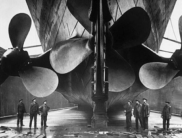
Ship Propellor

Propeller can be defined as: A mechanical device formed by two or more blades that spin around a shaft and produces a propelling force by converting rotational motion into thrust. The ship propulsion system along with the main engine, Thrust block, Shaft, Stern Tube and propeller works on the third principle of Newtons law. Thrust is generated by the propeller which in turn pushes the ship in the Forward direction.

There can be Two,Three or One propeller fitted on the ship depending on the ships requirement for speed, cost, maintenance and maneuverability.

Material and construction

Ships propellers are made up of corrosion resistance material (Nikalium) having different elements in following proportion:
Copper                   -      80.2 %
Aluminum              -      9.3  %
Nickel                     -      4.3  %
Iron                         -      4.0  %
Manganese              -      1.2  %

Types of Propeller:

The type of propellant used must be chosen early in the design process of the ship as the type of propellant, even have a strong influence on the design of the ship. Most ship screws are fixed pitch fixed-propeller types. But there are various types of propeller that one can use:
  1. Fixed pitch propeller
  2. Detatchable blade propeller
  3. Controllable pitch propeller
  4. Voith Scneider propeller
  5. Azipod type propeller
  6. Kort nozzle propeller
Fixed pitch propeller: A fixed propeller is propeller with simpler models and used on merchant ships. These types of non-traditional feast Propeller is made from individual casting. They usually have an efficiency advantage, cost, and simplicity compared to other types of propellers.

Fixed Pitch Propeller
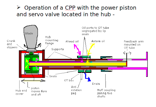
Controllable pitch propeller: Propeller type in which the propeller thrust direction is controlled by changing the pitch of the propeller is known as CPP. It is used to control the speed and direction of the boat/ Ship without changing the speed or direction of the main shaft of the ship's propulsion.

Advantages:

  1. Where the operating conditions vary widely and maximum thrust is desired throughout these operating conditions, such as tug, trawler and offshore supply boat applications.
  2. Where shaft reversing capabilities are not readily provided by main engine (e.g. gas turbines).
  3. Where extensive low speed maneuvering is required for a diesel powered vessel.
  4. Where the ship will operate in ice-covered   water. The unidirectional rotation of CPP subjects the Blades to less ice damage.
  5. When an improved maneuverability and a minimum ship stopping distance are desired. An infinitely variable thrust capability in either direction and a more rapid response to thrust reversal commands improve ship maneuverability and reduce the ship’s head reach.
  6. Where a constant shaft rpm is an advantage over wide range of operating powers.
Controlable pitch propeller

Disadvantages :

  1. It is a complex system hence reduced reliability compared to fixed pitch.
  2. With oil in propeller boss, possibility of pollution of sea with oil.
  3. Increased maintenance on the propeller and extra maintenance because of additional equipments involved.
  4. Chances of propeller blades getting stuck at some particular pitch angle and thus giving no choice to vary the magnitude of the thrust.

Working of CPP

The pitch of the CPP blades is controlled hydraulically through a system consisting of a pump, piston, crosshead, and blade crank rings. The piston, crosshead, and crank rings are located in the propeller hub. High pressure hydraulic oil, acting on either side of the piston, moves the piston axially within the propeller hub.

The piston is attached to a piston rod that connects to the crosshead that moves axially with the piston. Sliding blocks fit in machined slots on the crosshead and these sliding blocks fit over eccentrically-located pins mounted on the crank pin rings. As the crosshead moves forward and backwards within the hub, the sliding blocks move in an arc that also moves the eccentric pin and rotates the crank pin rings to which the CPP

Checks on propeller in Dry Dock

1. Physical damage to blades, specially on tips
2.Erosion/corrosion damage
3.Pitting due to cavitation
4. Local cracks or tears

Repairs on propellers in Dry dock

1.Straightening of blades by weights and levers while heating
2.Welding- Requires inert gas shielded arc and preheating for abou 1 hr at 120 degree C.
3.All slag,s to be removed between two consecutive welds.
4.Old repairs to be ground out before new repairs.
5.Propeller may be downsized by cutting portions from the edges on all blades as per class approval.
6.Cracks in the key to check and repair
7.To check for cracks on the boss and repair if required
8.Propeller surface to be polished
9.If required  Silicon coating to be applied after polishing the blade


Author Amit                                                                            Article Requested By: javed iqbal


Understanding Shaft alingment And its methods

Shaft Alingment ship
Shaft alignment is the process of aligning two or more shafts with each other to within a tolerated margin. Shaft system would ideally be installed with straight alignment and remain in that state during ship operation.But many factors affect and alter alignment during building and throughout the life of the ship example hull flexure due to  different conditions of loading (cargo, ballast, bunker, FW etc).

The hull of a moderately sized ship can flex 150 mm in heavy weather. High deck and low sea temperatures in the tropics cause differential expansion and hogging. Intermediate shaft is also subjected to variations of torque due to propeller racing as well as compressive stress due to end thrust from the propeller. Misaligned shaft imposes severe bending stresses on the shaft line. Also it will result in overheating of the bearings. Bending of intermediate shaft imposes severe stresses on coupling bolts, subjects them to additional shear stresses, leading to failures. Good shaft alignment guarantees correct loading of bearings and ensures that the shaft is not unduly stressed.

Difficulties in checking shaft alignment :

Shaft alignment for ships is very different from shore based engines because during alignment of shore based engines , conditions prevailing at sea are not present. At sea, number of external forces are continuously acting on ship structure which can cause limited amount of misalignment continuously. As long as this misalignment is with-in certain limits, shafting system works properly.

External factors affecting Shaft alignment readings:
  • List and trim of the ship
  • Mooring of the ship
  • SW temp & atmospheric temperature.
  • Temperature of liquids in D.B. tanks below bearings.
  • Un- availability of accurate precision instrument.
  • Bearing supports on tank top which may hog or sag.
  • Intermediate shaft is sufficiently heavy to sog.
  • Stern tube through which tail end shaft passes is slightly sloped 1:80 to avoid edge loading.
    Weight of propeller causes bending of the shaft.
  • Crankshaft & engine structures are rigid, only possible flexible length is intermediate shafting.
  • Shaft passes through many bulkheads. These bulkheads causes hindrance & difficulty while checking alignment.
  • A very bright light makes it difficult to get accurate alignment. Generally alignment is carried out in a dim light and in early hours of the morning.
Shaft Alignment methods:

(a) Pilgrim wire method
(b) Sighting by light method (optical telescope)


Shaft alingment piano wire method

(a) Pilgrim wire method: Produces fairly accurate results. Used where we can’t use sophisticated methods like method of Flexible wire having uniform weight over its length (piano wire) is used as a Reference line. Wire is tensioned to a standard amount by fixing at one end and having a weight over pulley at the other end.

Items required : a length of piano wire, Ball bearing pulley, anchoring or support clamp & weights.
Distance from wire to bearing are then measured either electronically or using micrometer. Allowance being made for sagging of the wire. Maximum sag will occur at the centre of the span if the pulley and support are horizontal. Flexible wire having uniform weight over its length, when it ends are supported ----- curved formed is a catenary which has certain mathematical property.


Author Arpit Singh                                                                           


Air Compressor maintaince and Troubleshooting

Air Compressor maintaince and Troubleshooting

In order for ships air compressors to work effectively, at any time, you should know what the most common problems can occur and their causes. You need to know how to take care of vents; How to hold and replace the air valves; Maintenance of pneumatic cylinders and pistons; And like the bearings adjust, crank pins and links. You should be able to replace and repair the lubrication , cooling, control and air systems.

AIR INTAKES

A clean, dry air is essential to the proper operation of the compressors. To do this, the air intake filters should be regularly inspected and cleaned; If the filter is clogged there is a loss of capacity. A clogged air screen or inlet filter can also lead to extraction of oil from a compressor crankcase, around the rings or through oil seals to cause an explosion. Remove the filter element and clean with a jet of hot water or steam or by immersing in a strong solution of sodium hydroxide. The filter housing must be drained and replaced. When the filters are soaked in oil, dipping in clean oil, intermediate and complete emptying must be done before the filter at the inlet changes. Do not clean the filter with petrol or kerosene! Vapors can accumulate and explode in the compressor or the receiver. Make sure that no rain or dew on the inlet side be present and a means to drain the water from suction tube be provided. The lines should be as short and direct as possible. To supply air compressor air to the divers, avoiding compressor absorbs every internal combustion engine exhaust. You should also avoid possible inlets fumes from the fuel tank, spilled oil or gasoline.

AIR VALVES

The inlet and exhaust must be clean and kept in good condition. The valves if have leakage are generally contaminated and cause a loss in capacity. Valves are removed by loosening the fastening screws or clamps and then removing the cover plates. Each relief valve , if provided, can be lifted. Each valve should be checked to ensure that it returns to the same port from which it was removed. The valves removed for inspection should not be removed for cleaning if the conditions so require. Usually, dirt or carbon in the valve hole can be removed without removing the valve. This is done by soaking the valves in kerosene, then giving a stiff, light brushing or light scraping. The action of the valve is to be tested by inserting a screwdriver through the seat opening; The valve must lift and close freely. If necessary, remove the valve, check the arrangement of the various parts so that the corresponding relationship is maintained with the valve assembly. (The periodic reports on board show damage to the piston and valve parts if connected poorly mounted valves in the way of the piston lugs protrude.) Before replacing the cylinder in a cylinder, replace the air valves, check the seals and replace them. Plates coated with copper or asbestos thin and thin copper. Alternatively, they can be used together of compressed asbestos temporary 1/16 inch. Each valve assembly is inserted into the same hole that has been removed. Since it may be difficult in many cases to distinguish between the suction valve and the pressure valve, care must be taken when the valves are inserted into the cylinder. Make sure the suction valves are open to the center of the cylinder and exhaust valves are clear. Failure to do so will result in serious injury or loss of capacity. Then, the valve cap in the cylinder ensures that the gasket is in place; Lower even coverage of nuts and again do not tilt the lid. Tighten the set screw of the valve or clamping screw, pulling the valve in its seat. If no special lock in the threads of the screw of the valve to prevent leakage leakage must be placed through a locking nut in a recess around the screw and placing welding or fuse wire.

CYLINDERS AND PISTONS

The cylinders on pistons should be inspected only AFTER the manufacturer’s technical manual has been consulted.   Be   careful   when   removing   heads,   particularly where metal-to-metal joints are involved, to prevent damage to the joint.
If replacement of piston rings is required because they are worn or broken, take accurate measurements of the cylinder liners. Standard size rings may be used in oversize cylinders if the oversize does not exceed 0.003inch per inch of cylinder diameter. The liner may also need to be replaced if it is badly worn or out of round. When replacing piston rings, first fit them to the cylinder to check for proper end clearance. You can file the ends, if necessary, to make them fit. The side clearance of the rings should be such that the rings will fall easily into the piston grooves, which should be deep enough for the ring thickness.  Ring splits should be staggered.  After you assemble the piston, wire the rings tight with a soft copper wire so that they will enter the bore easily. This wire can be removed through the valve ports after the ring has started into the cylinder bore.
When reassembling the air cylinders and heads, be sure  they  are  all  drawn  down  evenly,  especially on multistage   compressors   where   the   heads   contain cylinders  for  third  and  fourth  stages. Otherwise, the result will be excess wear on the cylinders and pistons.
When a compressor piston has been replaced, the piston end clearance must be checked. This is done by inserting a lead wire through a valve port or indicator connection. Jack the compressor over. When the piston has  moved  to  the  end  of  its  stroke,  the  lead  will  be flattened  to  the  exact  amount of  clearance.  The  wire should  be  long  enough  to  permit  a  reading  near  the center of the piston. These readings should be taken after any adjustment or replacement of the main, crank pin, wrist pin, or crosshead bearings. Methods of adjusting the clearances vary according to the compressor design. You should consult the manufacturer’s instructions for suggested   adjustment.

MISCELLANEOUS  ADJUSTMENTS 

From time to time other miscellaneous adjustments are  required  on  compressors,  including  those pertaining to  wrist  pins,  crosshead  shoes,  reduction  gears, couplings,   and   V-belt   drives.   The  manufacturer’s technical manual will give you specific information forth   care,   adjustment,   and  replacement   of   all   fitted bearings.  Refer  to  the  manufacturer’s  instructions  for detailed information  on  when  and  how  to  make  these adjustments.
Wrist pin bushings are replaced when necessary. This  is  done  when  they  are  worn  to  the  point of becoming noisy. In making a replacement, be sure the oil hole in the bushing is properly lined up with the oil hole in the connecting rod. After being pressed into the rod, the new bushing must be reamed.

Crosshead shoes are provided with shim or wedge adjustment.   Wear   should   be   slight,   but  adjustment should be made when the travel of the piston rod causes movement in the stuffing boxes.
Alignment of reduction gears and pinions should be checked periodically, especially on a new compressor. Misalignment  may  be  caused  later  by  settling,  straining, or  springing  of foundations; pipe  strains  on  turbine-driven compressors; bearing wear; or springing due to heat from a turbine.

Flexible couplings require very little maintenance when they are properly lined up.  Some types require occasional lubrication to prevent excessive wear of springs and bushings. A noisy coupling is an indication that the bushing is worn and requires replacement.
V-belt drives require adjustment for belt tension. Belts generally stretch slightly during the first few months of use. A loose belt will slip on the motor pulley and cause undue heating and wear on the belt. A tight belt will overload the bearings. Belts should be protected against oil and high temperatures.  To prevent rapid deterioration, belts should not be used at temperatures above 130°F. V-belts are usually installed in sets of two or three.  If a single belt is worn or deteriorated, the complete set should be replaced to ensure that each belt will carry its share of the load.

LUBRICATION SYSTEM

Proper care of a compressor lubrication system includes the following:-
  1. Keep the oil at a normal level in the reservoir at all times to maintain proper oil temperature.
  2. Change crankcase oil periodically, and at the same time clean and flush the crankcase and clean the oil filter.
  3. Maintain proper lube-oil pressure by keeping the oil pump in good working order and adjusting the bypass relief valve.
  4. Keep  the  oil  cooler  free  from  leaks  (since pressure  on  the  water  side  exceeds  that  of  the  oil)  to prevent oil contamination and emulsification.
  5. Properly adjust the lubricator for the specified quantity of oil feed.

COOLING SYSTEM

Proper  care  of  a  compressor  cooling  system includes  the  following  inspections  and  maintenance procedures:
  1. Periodically inspect the intercoolers and aftercoolers
  2. Remove  collections  of  gummy  oils  or  tarry substances from the cooler tubes by washing tube nests with  a  suitable  solvent  and  drying  them  thoroughly before reassembling.
  3. Correct any leakage in tube nests to prevent leaks of water into the compressor while secured or leaks of air into the water side during operation.
  4. Inspect and clean the cylinder water jackets periodically with a cleaning nozzle.
When  filling  the  cooling  water  system  after  the compressor  has  been  drained,  open  the  water inlet slightly to allow the water to rise slowly in the cooler shells and water jackets. Vent valves fitted to the water spaces should be opened to permit entrapped air to escape and to remove any air pockets.

CONTROL DEVICES

Because of the great variety of regulating and unloading devices used on compressors, you will have to  consult   the   manufacturer’s   technical   manual   for information regarding the adjustment of these device son particular compressors.
If a control valve fails to work properly, it should be taken apart and cleaned Some valves are fitted with filter  filled  with  a  sponge  or  woolen  yarn  to  prevent particles of dust or grit from being carried into the valve chamber. These filters remove gummy deposits from the oil used in the compressor cylinders. When repacking, use only genuine wool. Cotton will pack and stop the airflow.  Relief   valves   are   very   important   for   safe compressor operation. They should be set as specified by the manufacturer and lift-tested by hand each time the compressor is placed in operation.  To check the setting periodically, test by raising the pressure in the spaces to which they are attached.

SUMMARY

Since an Engine man may encounter so many types of   compressed   air   systems,   air   dryers,   and  air compressors both ashore and aboard Navy vessels, this chapter presented only general procedures and facts.  To maintain, repair, and overhaul specific compressed air systems,  air  dryers, or reciprocating  air  compressors, you  must  refer  to  the  manufacturer’s  technical  manuals. A  definite  preventive   maintenance   schedule   with frequency and assignment of responsibility is required. You should have the manufacturer’s manual handy to establish   minimum   requirements  and   to   follow   its recommendations for maintenance.


Author Amit                                                                            Article Requested By: Rauhjek


Seawage treatment Plant on board ship | Explained

Seawage treatment Plant on board ship

The discharge of untreated sewage in controlled or territorial waters is usually banned by legislation. International laws is in force to cover sewage discharges at certain distances from the earth. Accordingly, and to meet certain standards, all new ships have installed sewage treatment plants.

Two types of sewage treatment plants are used, using chemical or biological methods. The chemical process is essentially a reservoir that collects the solids for disposal in authorized zones or areas collection site. The biological process treats waste water, so it is acceptable to discharge near the coast.

Legal Regulations and  Ship’s  Sewage Discharge

Unloading the sewage and storage of sanitary water from ships and equipment and containers must be certified to meet the prescribed standards, it has been regulated according to national and international standards. The problem of marine pollution by ships is the International Convention for the Prevention of Pollution from Ships, 1973-1978 (MARPOL 73/78) introduced by the IMO.
MARPOL lays down rules and regulations that prevent downward marine pollution by using oil, chemicals, harmful substances in any form of packaging, waste water and waste, harmful gas emission and ballast.

The Convention comprises of a number of Annexes and Annex IV contains provisions regulating prevention and supervision of marine pollution by sewage waste waters from ships. Annex IV to the Convention refers to:
a) prohibiting or limiting discharge,
b) issuance of certificates and inspections,
c) equipment and supervision of discharge,
d) shore reception facilities.
MARPOL Annex IV, is applicable to ships on international voyages that are 400 gross tonnage and greater; or less than 400 gross tonnage when certified to carry more than 15 persons. The board discharge monitoring equipment should include at least one of the following sewage systems: 
  • The sewage treatment plant will be managed by the administration taking into account the standards and testing procedures of the IMO.
  • A grinding plant and waste water disinfection approved by the administration.
  • Such a system will have for the temporary storage of sewage systems to the satisfaction of the administration, if the ship less than 3 miles from the next country.
Annex IV of MARPOL 73/78 (IMO) regulates the disposal of ships at international level. In addition, some countries have their own national and regional controls.

The board discharge monitoring equipment should include at least one of the following sewage systems:
The sewage treatment plant will be managed by the administration taking into account the standards and testing procedures of the IMO. A System liquidation and waste water disinfection approved by the administration. Such a system will have for the temporary storage of sewage systems to the satisfaction of the administration, if the ship less than 3 miles from the next country.

The Hazards and regulations regarding the Sewage Systems:

Water drainage and waste water narrow limits reduce the ability of self cleaning. You can see in the sediment to the water, along with hydrogen sulfide has a pungent smell. The combined hydrocarbon and carbon stimuli plant oxygen back into the water.

With less oxygen, the best aerobic bacteria or infections cause anaerobic bacteria to rise due to lack of oxygen and so requires a control. Together with the decomposition solution and the smell of decay and its process produce  gas (toxic). Consequently, the action of packing station a group of aerobic, is necessary for type of waste water.

Principle of Biological Treatment Plant

The system require slow and steady fluid flow. The accumulation of heavy slime is a problem even , longer stay in the aeration chamber significantly reduces the cost. For example, 80% of the waste water contains solid reduced waste after 12 hours of aeration tanks in 20% of its original weight.

The aerobic process to remove dissolved oxygen in water generates water, carbon dioxide and bacteria.

Operation of Biological Treatment Plant

Image Source : http://www.marineengineering.org.uk (Used For reference purpose only)

The above plant shown has 3 chambers. The sewage enters the aeration chamber through a coarse filter where large solids decomposes, Then it goes to the ventilation chamber  where the main biological effect takes place. Here air blower mounted on the sides of the unit used to pump in air for the survival of aerobic bacteria, product flow of oxygen and bacteria was stirred through a series of pipes and nozzles. Then the waste is in the aeration pool for a sometime.

Move sewage from settling basin (or funnel) into the biological flocculate under resting conditions, aeration enters and bacteria settles and to the aeration chamber by pumping air by using blowers. A second transfer line is from the surface of the settling basin and extends to the aeration chamber. This transfer mud which contains bacteria that the waste water enters to digest.

Safety Parameters:

Anaerobic bacteria in all forms in a given situation, give away toxic and flammable gases. There is a need to participate in reducing the required anaerobic in treatment plant. You can carry the gas freeing so it can not enter the damage limit.

Here are some ways you can help reduce the risk:
Use air bathroom to reduce the risk. There must be a positive pressure in the chamber at all time to avoid any further gassing and risk of aerobic bacteria to die out. When the water storage tank is flushed out, maintain a system of oxygen in the water. For example, it can be entrained in the water so can be injected directly into the air, or air is pumped in. You should check the container. If you use aerobic treatment device, always check that the direction of operation of the plant should be considered positive. You should refer maintenance system whenever needed.

Maintenance of Aerobic treatment units

  1. Check for regular cleaning and care being paid to areas behind internal division plates
  2. Checks on alarms and trips
  3. Checks on aeration equipment
  4. Checks on transfer systems in the tanks
  5. The chlorination of the sample should be between 1-5 ppm
# Various books, study material and other online sources has been refereed prior to writing this article but no part is copied or produced  from any of the source but explained same thing in better detailed way.

Author Amit                                                                            

Merchant Navy: Decreasing jobs, salary and long contracts What's the way ahead?

Merchant Navy: Decreasing jobs, salary and long contracts What's the way ahead?

The BIMCO / ICS 2016 report of the world-wide research on man power supply in the Merchant Navy has found very disappointing statistics about Crew / Rating. The demand for crew in the market is low and supply is high. According to their estimates, there are more than 1,19,000 crew supplies. In the last 10 years, no increase in crew jobs has been found. Ratings have increased by just 1% in 10 years of jobs.

This research has been done on currently working vessels. Ratings that are being supplied by all the new institutes that are opened recently, make the situation more worrisome.

With this, China and the Philippines have also raised concerns about the international / Indian crew. Most foreign companies have turned to China for the crew. China is currently supplying more crew than the Philippines. In such a situation, the possibilities for shipping to the crews of other nations are decreasing.

Shipping companies have begun to take advantage of these conditions. Another, where the crew's salary is being reduced, their contract has also been enlarged. Facilities have already been reduced. Most shipping companies are now refusing to give the crew separately overtime. Some companies have started reducing the salaries of the crew working on the ship.

It is very difficult to find a job now a days for freshers who have come to the market by doing a GM rating course. Most of these people are only trapped in the affair of agents and only waste their money. Agents either disappear by taking money from these or send them to some Gulf counties for a maximum of one contract. After coming back, they have to wander again for their jobs and find no job security.

What to do? How to raise your career forward?

According to the BIMCO / ICS report, the supply of not only the Crew of shipping has remained high, but the jobs are going higher in China and the Philippines, rather than coming to any other country say India or Spain. In view of this, there is a possibility of a lot of improvement in the Crew's job in the future, but due to more supply, the conditions are likely to worsen. In such a situation, Indian crew members along with other world communities should also pay attention to jobs coming in other areas.

Career prospects in NCV / OFFSHORE / TUGS / HOME TRADE ships

Another, where jobs are being reduced in overseas shipping companies and large ships, on the other hand, there are floods of jobs in home trade ships. The way the Indian government is investing in Port Sector and Inland Transport, and encouraging this. Because of the huge increase in the ships operating in this area,  the jobs coming in them are also increasing very much.

Similar government programs to push for offshore vessels or short range vessels are under way in many developing and developed countries in the world.

The best part of it is that the crew can also become an engineer or master by giving NCV EXAMS further. Presently the demand for NCV Master and Engineer is very high, as well as their salaries have also become very high. NCV Master is looking for salary of one and a half lakh rupees, and NCV chief engineer is paying salaries up to Rs 300000.(For India Only)

Contract ships are also available in India and different countries for up to 2 months, which is quite small, as well as the ships are very close to the coast, the phone and the Internet are available to you 24 hours a day. Due to the internet and the phone you have, you do not feel far away from your family and are connected to your friends for a whole time. Also, the contract periods is also less, which also causes your family life better.

In the beginning of the NCV ships, there is lesser salary, which is about 15 thousand rupees per month. But as soon as you clear the exam, this same salary goes up to Rs. 60000. The job security is high because of the low supply still in the NCV ships, salariers are also much more. Once you become an officer or an engineer, you also get more jobs and salaries are much more.

In view of the difficulties being faced in global shipping and jobs for the crew are declining, Indian crew members should look at this NCV ships and global crews should focus on offshore vessels, and if the opportunity is available then the career switch should also be done.

#Cover Image Source :www.ahlers.com (Used for reference Purpose Only).

#Note: The following article is property of ( Marine Republic) http://www.marinerepublic.in  and re-used with few modifications after taking due permission.

#Source:  http://www.marinerepublic.in/2017/03/blog-post_14.html

Watch Keeping at sea for Marine Engineers | Step-by-step


Watch keeping is an integral part of marine engineer’s duties on board ship. The technicians perform tasks and routines for monitoring the ship's engine room. The clocks are divided into three periods of four hours and the following work must be carried out and checks carried out at sea.

  • Check the colour of  exhaust emission from funnel.
  • Check the Economizer temperatures, pressure drop and the system for any leakage.
  • Check the oil fired boiler water level, blow through gauge glass and check pressure.
  • Check the boiler circulating pump for operating pressure, vibration, noise, gland leakage and bearing oil level.
  • Check and confirm normal operation of incinerator if running.
  • Check the waste oil tank level and temperature, drain off water.
  • Check Main & Aux. engine header tank levels, if they require filling record the quantity of water added.
  • Check the temperatures and pressure of the fuel valve cooling system. Examine the level of the F. V. C  header tank, check for contamination and confirm through flow.
  • Check stern tube header tank level, return flow, sump, pump and oil condition.Examine M. E cylinder tops for leakage, movement, overheating and any temperature or pressure outside the normal parameters.
  • Check for exhaust gas leaks.Examine turbo charger oil levels, pump operation, temperatures, pressures and differentials, whilst checking also for any unusual noise or vibration.
  • Monitor air cooler pressure drop, and ensure Makers operating parameters are adhered to with regard to dew point temperature.
  • Check cylinder oil day tank level and individual lubricators for level, flow and function.
  • Check all bunker fuel tanks for level, temperature and drain for water.
  • Check fuel fine filter differential.Examine fuel pumps for leakage or unusual noises.Ensure oil mist detector is functioning correctly and test alarm.
  • Check ME governor oil level and fuel pump racks.
  • Examine auxiliary blower if running and scavenge belt to ensure that scavenge and air cooler drains are clear.
  • Feel over scavenge belt.Test air line drains for water.
  • Check all standby pumps are on auto mode and ready to start.
  • Check air compressor  oil level, and the temperatures and pressures whilst  running.
  • Check fresh water generator for normal operation & also chemical dosing to feed line.
  • Check sewage treatment plant for normal operation.
  • Examine A/E and check all running parameters are within limits. Fuel leakage, non fitting of double skin pipes and removed  protection or insulation from exhaust manifolds to be rectified immediately .
  • Check A/E bilge’s for leakage.
  • Confirm that an alternator engine is on standby in the control room and that the L. O priming pumps are on Auto.
  • Checking drinking and domestic water hydrophore systems for levels, and leakage. Ensure that the Calorifier, circulating pump and UV Sterilizer are operating satisfactorily.
  • Examine boiler feed water system for normal pump operation and check the cascade tank for temperature and level. Also check that there is no hot well contamination with fuel oil due fuel oil heating coil leaks.
  • Examine air reservoirs and check the drains for water, ensure that control and service air reducing valves are functioning correctly and that the control air dehydrator is operating normally.
  • Examine the purifier room for leakage, ensure that running purifiers and operating normally with regard to oil levels, flow rates, temperatures and pressures. 
  • Ensure lowest throughput for L O purifiers.Check Calorifier.
  • Examine Booster pumps, flow-meter and heaters for normal operation without leakage.
  • Ensure that all main engine pumps are running normally and that standby pumps are ready for Auto operation.
  • Check HFO Serv & Sett tanks levels and temp. Drain off water.
  • Check all running purifiers for normal operation. Check gear case oil level, Separated Oil temperature and feed rate, motor load etc.
  • Skim off sludge from recycle tank.
  • Check F. O booster p/p, check F. O temperature.
  • Check JCW pump and motor for normal operation.
  • Check M/E Lubricating Oil Pressure (Bearing), X-Head Oil Pressure and Piston Cooling.Check piston cooler and L. O cooler in/out temp.
  • Check sounding of all sludge tanks, bilge storage tanks, compare with previous sounding.
  • Check M/E L O pump discharge filter Pressure drop.
  • Check M/E L O pump/motor for normal operation.
  • Check thrust bearing L. O temperature Fwd/Aft.
  • Check E/R bilge level with special attention under the flywheel.
  • Check L. O levels and temps of intermediate shaft bearings.
  • Check stern tube L. O sump level, oil pressure, temp and return flow.
  • Check M/E L. O sump sounding. compare with earlier soundings recorded.
  • Check and confirm L. O purifier is operating normally note L. O temperature.
  • Check piston cool leak off tank, open skimming v/v to skim off oil from top.
  • Check piston cooling water tank level top up if required.
  • Check and confirm main S. W p/p, motor and auxiliary  S. W pump/motor working normally.
  • Check piston cooling p/p pressure and in/out temp of all units check flow.
  • Check A/E load and winding temp. Do a function test on alarm panel. Reconfirm all running parameters of M/E and A/E.
  • See the Chief Engineer’s standing instruction book and also notice board for daily instruction and guidance. Discuss with outgoing watch keeping engineer if there have been any special operations problems during his watch or any change in status of running machinery Function and lamp test of Alarm panel.
  • Check no alarms are inhibited.Ensure no alarms indicating abnormal condition are active.
  • Ensure air and water on deck shut if not required.
  • Log down all parameters in log book
  • Check for following hazards and rectify :-
  • No Fuel, L. O or water  leaks.
  • No loosely stowed equipment.
  • Gas bottles shut and welding plant shut down.
  • Fuel high pressure pipes for M/E & A /E’s secure and no leaks.
  • No abnormal vibrations of any type.
  • No water tight openings open unnecessary.
  • Ensure that the welding equipment is off.Double check additional A/E on standby, and Emergency Generator on Auto.
  • Double check M. E controls on Bridge and max speed limit set as per Chief Engineer’s instructions
  • Check no alarms have been isolated, unless authorized by C/E and E/O. Note there are no existing alarm condition, unless a valid reason and C/E and E/O aware of.
WHEN IN DOUBT DO NOT HESITATE TO CALL CHIEF ENGINEER


Author Amit                                                                            


Psychology (Marine Engineers)

Marine psycology

As per the new guidelines of D.G Shipping, Subject Psychology is to be inculcated in the Syllabus of Marine Engineering.

Psychology

Definition: Psychology is scientific study of Human and Animal Behavior.
“It’s is define as scientific study, because it’s proven by scientific experiment on being”
“why animal behavior? You ask. Because some experiment cannot be performed on Human”

Psychology is divided into (By Nature) :

i)  Pure (Theoretical)

ii) Applied (need I say, it is applied and actually seen)

Psychology is divided into (By Branch) :

  1. Clinical Psychology
  2. Criminal Psychology
  3. Industrial Psychology
1) Clinical Psychology : it is to find mental disorder, as a shippie it’s worthy to note that almost 70% of people onboard a vessel get Depress at some point. Depression is a Medical Disorder, and when you’re depress, your body dehydrate faster. In Cold Climate and because of Blue colour of the Sea Depression is common (it’s psychology, temperature and colour has impact on us)

2) Criminal Psychology : it is to find out the psychology of criminal, why did they do what they do, people involve with this branch of psychology, stay in prison(not with the convict) but a room near there subject to study and make out the pattern.

3) Industrial Psychology : “the branch of applied psychology that is concerned with efficient management of an industrial labor force and especially with problem encountered by worker in mechanized environment”, also known as Organizational Psychology .

As we’re talking about ships, we’ll look only into Industrial Psychology

Definition: it is defined as the branch of applied psychology that is concerned with the efficient management of an industrial labor force and especially with problem encountered by worker in mechanized environment.

Aim of Industrial Psychology:

1. Increase worker productivity.

2. Design safe work environment.

3. Train new employees.

4. Help organize the company’s management structure.

Explained :
  • Increase worker productivity: One of the main goals of Industrial Psychology is to improve worker productivity. Industrial psychologists research workplaces to find ways to increase worker satisfaction and boost productivity. Industrial psychologists design and implement workplace procedures in order to improve employee efficiency.
  • Design safe work environments: Another function of Industrial Psychology is to design safe workplaces. Industrial psychologists study the company's operating procedures, equipment used and types of work performed to determine ways to make employees safer.
  • Train new employees:  Industrial psychologists are often in charge of creating orientation and training programs for new employees. They apply concepts of Industrial Psychology to create programs that teach new workers about a company's operating procedures and business philosophies in ways that make employees feel welcome and valued.
  • Help organize the company's management structure: Industrial psychologists can direct companies to reduce unnecessary redundancy and increase accountability. They can create organizational structures that clearly define the job duties and responsibilities for each position.

Author Arpit Singh                                                                 Article Requested By: Akul gupte


Basics of Main Air compressor on board Ship

Main Air compressor

Main Air compressor on ship is used to produce service, control and starting air. In the following article we explain the introduction, working and maintenance done on Main Air compressor.

What is a compressor?

A compressor is a machine capable of compressing and delivering the air at desires pressure and is driven by a prime mover(Engine or a electric motor). A compressor takes in atmospheric air, compresses it and delivers the high pressure air to a receiver(storage vessel) from which it may be conveyed by a pipeline.

Applications of compressed air on Ship:

  • For control air and service air application on board ship.
  • For various automation and controls, general service applications.
  • For starting main and auxiliary engines
  • To supercharge IC Engines
  • painting and spraying.
  • For operating pneumatic hand tools such as rivet sets, drills..
  • To operate air brakes in automobiles , ram lifts and pneumatic conveyors.
  • To blow air.
  • To transmit power for operation of machines.
  • To clean machines and work shop floor

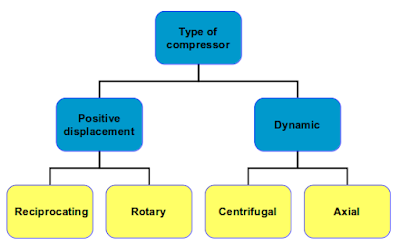
Types of Compressors: 

Types of compressors

Types of air compressors in use:
  1. Reciprocating  Compressor
  2. Centrifugal Compressor
  3. Screw Compressor
  4. Rotary compressor
  5. Diaphragm compressor
Classification of Air Compressors -

1.According to working: Reciprocating compressors, and (b) Rotary compressors.

2.According to action: Single acting compressors, and (b) Double acting compressors.

3.  According to number of stages: (a) Single stage compressors, and (b) Multi-stage  compressors.

Main Components in Compressed Air Systems:

  • Intake air filters
  • Inter-stage coolers
  • After coolers
  • Air dryers
  • Moisture drain traps
  • Receivers

Reciprocating Compressor:

The first commercial piston compressors were built in the middle of the last century, and evolved from the steam engines which provided the prime mover. Construction at first was double acting, but there was difficulty in maintaining gas-tightness at the piston rod, so the design evolved further into a single-acting machine.

The stroke/ bore ratio has diminished to the point of becoming fractional because of improvements in valve design and manufacture. Machines of four, six and eight cylinders arranged in either V or W formation are common. These are arranged in a multi bank configuration with two, three or four connecting rods on the same throw of the crankshaft to give a short, rigid machine.

This construction gives a large number of common parts – pistons, connecting rods, loose liners and valves through a range of compressors, and such parts can be replaced if worn or damaged without removing the compressor body from its installation.

Reciprocating Compressor

Working Cycle

The general form of positive displacement compressor is the piston type, being adaptable in size, number of cylinders, speed and method of drive.

It works on the two-stroke cycle, as the piston descends on the suction stroke, the internal pressure falls until it is lower than that in the suction inlet pipe, And the suction valve opens to admit air from atmosphere. At the bottom of the stroke, this valve closes again and the compression stroke begins. When the cylinder pressure is higher than that in the discharge pipe, the discharge valve opens and the compressed air passes to the air bottle. Clearance air left at the top of the stroke must re-expand before a fresh charge can enter the cylinder.

Reciprocating compresor indicator diagram

Single stage Compression

  1. It suffers the following drawbacks:
  2. The size of the cylinder will be too large.
  3. Due to compression, there is a rise in temperature of the air. It is difficult to reject heat from the air in the small time available during compression.
  4. Sometimes, the temperature of air, at the end of compression, is too high. It may heat up the cylinder head or burn the lubricating oil.
In order to overcome the above mentioned difficulties, two or more cylinders are provided in series with inter-cooling arrangement between them. Such an arrangement is known as multistage compression.

Advantages of Multistage Compression

Following are the main advantages of multistage compression over single stage compression.

  1. The work done per kg of air is reduced in multistage compression with intercooler as compared to single stage compression for the same delivery pressure.
  2. It improves the volumetric efficiency for the given pressure ratio.
  3. The sizes of the two cylinders (i.e. high pressure and low pressure) may be adjusted to suit the volume and pressure of the air.
  4. It reduces the leakage loss considerably.
  5. It gives more uniform torque, and hence a smaller size flywheel is required.
  6. It provides effective lubrication because of lower temperature range.
  7. It reduces the cost of compressor.
  8. In commercial shipping industry, highest air pressure requirement is about 30 bar (M/E starting air).
It is a standard practice to use two stage reciprocating compressors on board ship to satisfy all compressed air requirements on board ship.

Two stage compressor

Operation and maintenance:

Compressors must always be started in the unloaded condition otherwise pressures build up rapidly producing very high starting torques. During running there is an accumulation of oil carried over from the cylinders and water from moisture, precipitated in the coolers.

The emulsion is collected in separators at cooler outlets and these must be drained off regularly, to reduce carry over. This is extremely important, first to prevent any large quantity of water and oil emulsion reaching a subsequent compression stage and causing damage to a further stage and secondly to reduce the amount carried over to the air receivers and starting air lines.

Moisture in air receivers can give rise to corrosion and despite the proper operation of compressor cooler drains, a large amount tends to collect, particularly in humid conditions or wet engine rooms. It is good practice to check air reservoir drains regularly to access the quantity of liquid present.

In extreme conditions, drains may have to be used daily to remove accumulated emulsion. This is very important if air for control systems is derived from the main receivers, to prevent problems with the reducing valve, moisture traps and filters.

Moisture traps for the control air system also require regular checking and possibly daily draining. A compressor is unloaded before stopping by opening first and second stage drains.

Effect of Choked Inlet Filter

Safety Devices:

  1. Relief valve fitted to every stage
  2. Fusible plug   (melts at 120°C)
  3. Bursting disc or relief valve for cooling jacket
  4. Alarms and cut outs for:
    • High air temperature
    • High cooling temperature
    • Low lubricating oil pressure

Author Amit                                                                            Article Requested By: Abhishek Verma


How to prevent oil spillages and leakages during bunkering operation

Bunkering on ship

Oil spills and leaks in fuel operations are an important source of contamination from discharges from ships. Experience has shown that most of the bunkers spill and overflow, which can be attributed to human error.

It is important that all operations are carefully planned and fuel runs. It is to be noted that due to the heavy oil spill pollution is particularly harmful and difficult to clean.

The personnel involved in the bunkers on board does not have to have other tasks and must remain at their jobs during the filling process. This is particularly important when the simultaneous loading with loading cargo, should avoid conflicts of interest between the operating staff.

Safe storage procedures:

Ship operators should require that all fuel operations are controlled in a process that is part of the ship safety management systems. The procedure must ensure that it is linked to the risks associated with the operation and controls in place to mitigate these risks. The procedure should also take into account emergency measures for loss containment. The operator should take into account when developing the process:

1. Determine that there is enough space for the volume of loaded cargo spaces.
2.Controls for the system valves hold.
3. Determination of the load factor for the beginning of the load, mass and auction sold.
4.Arrangements of bunker tank ventilation.
5.Tank overflow internal arrangements.
6.Setting alarm override alarm units.
7. Communicate with the terminal to determine when you are making fuel.
8. Communication Provider Bunker before the loading process to establish and start recording and how the quantity and quality controls can be carried out, especially if secure access between the ship and a barge is required.
9. Bunker management practices have dealings or may have a H2S salary.
10.Testing procedure to determine the presence of hydrocarbons or H2S vapor.
11.Method Determination temperature Bunker during charging.
12. A communication procedure for operation, including the emergency stop.
13.Monitoring of the bunkering operation and checking it conforms to the agreed procedure
14.Changing to tanks during charging.
15. Establish a maximum load volume for all reservoirs.
16. Special precautions for loading in double-bottomed tanks.
17. Having made arrangements for retention and cleaning equipment.
18. Requirement management to ensure safe operation.

After the intervention, a checklist must be implemented.

Bunkering Safeties and responsibility

Responsibility of personnel engaged in bunkering operation:

The staff on board who is appointed to manage the operation of the fuel should not be involved in other operations. Spills are often caused by the staff distracted from another task. Before the start of the operation carried out all the controls and preload checked communication systems the work. The loading rate should be checked regularly.

Care should be taken when switching from tank to tank to ensure that excessive pressure is not applied to the rows of pipes or load. When filling tanks, it reduces the loading speed, reduce the possibility of air pockets in the container to the mist caused by the ventilation openings is transported and to minimize the risk that the supplier is enough to not stop quickly.

At the end of loading, all pipes and hoses should be drained before being separated into the tank or, if necessary, back to the barge. The practice of air ducts in the fuel tanks blows is common but a high risk of causing a spill when the tank is full and has only enough space to end the load.

To the responsibility for the security of the operations, while a ship bunker reception barge is shared the captains of the tanker and barge jointly. Fuel exploitation of responsibility is usually delegated to certain officials responsible for the boat and the barge. Before the bunking commissioning, the responsible should:

•Agree in writing on the handling procedures including the maximum transfer rates.
•Agree in writing on the action to be taken in the event of an emergency during transfer operations.
•Complete and sign the Bunkering Safety Check List.

Safety Manual List Bunkers Tax

The checklist uses security bugs to assign responsibility and accountability. Acceptance is confirmed by ticking or part of the box and finally signing the declaration. Once signed, the minimum basis for safe operation agreed by the mutual exchange of critical information is described in detail. Certain statements in the checklist are considerations that the ship is solely in charge of and responsibility, some of which the barge's sole responsibility and liability and other attribute responsibility and shared responsibility. The gray grades are used to identify statements that are not universally applicable to a party, even if the ship or the barge can create such sections if they so wish.

The division of responsibility and accountability does not mean that the other party's behavioral examinations exclude compliance. The division of responsibility and accountability allows a clear identification of the party responsible for the first compliance and continuing education throughout the transfer activity.

The responsible persons completing the checklist should be the people carrying out the bunkering operation.

The tankers representative should personally check all considerations lying within the responsibility of the tanker. Likewise, all considerations that are the responsibility of the boats must be personally monitored by the representative of the barge. In their responsibility, representatives must ensure that the security standards on both sides of the transaction are acceptable. This can be achieved by means such as:
i) Confirming that a competent person has satisfactorily completed the checklist.
ii) Sighting appropriate records.
iii) By joint inspection, where deemed appropriate.

Before the start of operations, and sometimes for mutual safety, member barge of the staff and, if necessary, a responsible official will perform inspections of the barge and carry out the vessel to ensure that his obligations, list, they are treated effectively.

The safety cabin list contains the following sections:

1. Bunkers to be transferred

A joint agreement on the amount and degree of the bunker transferred and the agreed transfer rate and the maximum return pressure.

2. The fee for the loading tanks

Identification of bear tanks sufficient space to ensure it is safe to transfer the bunker. A space for receiving the maximum filling volumes of each container and the volume provided.

3. Control barge before going to berthing

This section will be checked before the ship is next to the ship.

4. Checks before transfer

This section will perform controls to be presented jointly before the transfer activities.

Check list

Safety checks prior to berthing

1. The barge has obtained the necessary permits to go to the receiving container.

2. Mudguards have been checked, are in good condition and there is no way to metal against metal contact.

3. When fairly reasonable electrical insulation compound be present on the barge / boat.

4. All keep hoses in good condition and are suitable for the desired service.

5. The Ship is safely anchored.

6. It is a safe means of access between the ship and the barge

7. Effective communication has been placed in the place between the officials. (VHF / UHF .......... Ch)
Primary System: Backup system: emergency stop signal .

8. It is an effective clock on the barge and ship storage bunkers.

9. Firefighting hoses and fire extinguishers against fire on board the barge and the vessel are ready for immediate use.

10. All culverts are blocked. Detachable connectors at all times. The drip cups are in position around  the fuel tank vent openings.

11. Bunker connections are empty and completely screwed.

12.The transfer hose is properly rigged and fully bolted and secured to manifolds on ship and barge.

13. The valve housing is connected to the charging system, the holder of the engine compartment and bunker lines is closed and sealed.

14.All cargo and bunker tank hatch lids are closed.

15. The content of the bunk tank is not monitored at intervals. Supply oil spill clean

16.There is a supply of oil spill clean up material readily available for immediate use.

17. Radars are switched off.

18. The radio is in low power.


Author Amit                                                                                      Article Requested By: David


Comparison between shell and plate type Heat Exchangers

heat exchanger

Both the Shell and Tube and Plate Type heat exchangers work with the same principles, exchanging heat between two fluids through thermal conduction, but with very different construction methods. Both plate type and shell and tube heat exchangers are normally used on ships and have their advantages and disadvantages.

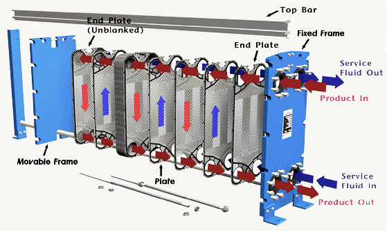
Plate Type Heat Exchanger
Advantages

1. Simple and compact in size.
2. Heat transfer efficiency is more.
3. Can be easily dismantled for cleaning.
4. No extra space is required for dismantling.
5. Capacity can be increased by introducing plates in pairs.
6. Leaking plates can be removed in pairs, if necessary without replacement.
7. Maintenance – cleaning is difficult (as surface is visible).
8. Turbulent flow help to reduce deposits which would interfere with heat transfer.

Disadvantages
1. Initial cost is high since Titanium plates are expensive.
2. Finding leakage is difficult since pressure test is not as easy as tube coolers.
3. Bonding material between plates limits operating temperature of the cooler.
4. Pressure drop caused by plate cooler is higher than tube cooler.
5. Careful dismantling and assembling to be done.
6. Over tightening of the clamping bolts result in increased pressure drop across the cooler.
7. Joints may be deteriorated according to the operating conditions.
8. Since Titanium is a noble metal, other parts of the cooling system are susceptible to corrosion.

Shell and Tube Heat Exchanger

Advantages
1. Less expensive as compared to Plate type coolers.
2. Can be used in systems with higher operating temperatures and pressures.
3. Pressure drop across a tube cooler is less.
4. Tube leaks are easily located and plugged since pressure test is comparatively easy.
5. Tubular coolers in refrigeration system can act as receiver also.
6. Using sacrificial anodes protects the whole cooling system against corrosion.
7. Tube coolers may be preferred for lubricating oil cooling because of the pressure differential.


Disadvantages
1. Heat transfer efficiency is less compared to plate type cooler.
2. Dismantling for maintenance is difficult since a tube cooler requires enough clearance at one end to remove the tube nest / accommodate the lancing tool and the end covers are relatively large & heavy.
3. Capacity of tube cooler cannot be increased.
4. Requires more space in comparison to plate coolers.
REFERENCE SOURCE: 
“General Engineering Knowledge” by H.D. McGeorge


Guest Author Name: Aditya Malik
Social Profiles: ?
Short Bio: Trainee marine engineer opting for m.tech in marine engineering in U.K.


* The following article is partly produced as it is from Reference source for better understanding. Nor the blog owner or other permanent authors are responsible for any copyright claims. Inform us if you have any problem with the content.

Conventional fresh water cooling system | Explaned

Conventional Fresh water system

The machines installed on ships are designed to work with maximum efficiency and performance for long hours. The heating energy should be so reduced or heat transfer be increased by a cooling means to avoid a malfunction or a machine failure to prevent. For this reason the cooling water systems are installed on ships.

While there is an abundance of seawater available, marine diesel engines do not use it directly to keep the hottest parts of the engine cool. Instead, the water flows to the engine is fresh water, which is then cooled by seawater.

The engine cooling is achieved by circulating a cooling fluid around the internal passages in the engine. Therefore, the coolant is heated and itself cooled by a cooling flow of seawater. Without adequate cooling, parts of the engine, which are exposed to very high temperatures can be damaged so fast. The engine cooling allows metals to maintain their mechanical properties. The lubricating oil is sometimes used for cooling the piston, as a leak in the crankcase will not cause any problems.

Here a cooling system with fresh water  for low diesel engine speed is displayed. It is divided into two separate systems, one for the cooling coats of cylinders, cylinder heads and turbo blowers; The other for piston cooling.

The cooling water of the cylinder, after leaving the engine via a seawater cooler and circulation pump then turn the water circulation. Then pumped around the cylinder body, cylinder heads and turbo blowers/chargers. A head cap or expansion tank allows water to expand and system make-up. Venting openings are driven by the engine to the head of the reservoir for water from air exhaust cooling. A heater in the circuit facilitates the engine pre-heat in front of the hot water circuit.

The cooling system uses components similar to pistons, except that the drain tank is used instead of a head tank, and vent openings are performed at high points in the engine room. A piston cooling system
Only used to limit the contamination of the piston piston cooling glands.


Author Amit                                                                                      Article Requested By: Alice

* Various sources has been refereed before producing this post both online and offline but no part is reproduced except for the image (for reference purposes only).