How to do crude oil washing on ships in 10 easy steps

How to do crude oil washing on ships in 10 easy steps

COW or Crude Oil Washing cleans cargo tanks with jets of high pressure oil when the ship is unloaded. The crude oil is pumped through the washing machines to the jets and serves as a cleaning agent which is then pumped to land with the load/Product Discharge. It has been found that crude oil is more reliable washing medium than water. The washing / dissolving effect results in heavy, waxy and asphaltic deposits on the sides and bottom of the Holding tank to convert back into the liquid so that they are easily discharge To the shore. The Crude Oil Washing (COW) techniques has several advantages over washing with water, using Cow as the washing medium reduces the Sludge deposition, thereby reduces the discharge (Stripping) time and increasing the load/cargo flow. There low deposition of mud at the bottom of the tank which reduces Ship constant and so increase its dead weight. On the other hand washing with water takes more time due to more deposition of mud at the bottom. They not only cause delay in washing but also release hydrocarbon gases which becomes a challenge to gas free the tank. There are three essential prerequisites for the washing of petroleum product:

A fully functional inert gas system for maintaining the tank atmosphere in an inert state during the whole wash cycle.
Fixed Piping Lines for Tank washing system
Means to ensure that the bottom of the tank is clean and dry at the end of the operation.

The vessel must be equipped with an inert gas system which can function properly and produce Inert Gas with a maximum oxygen content of 5%. This should be maintained during the COW to ensure that the oxygen content does not exceed this value. No COW operation to be performed if the Inert Gas installation of the ship is not working properly and the oxygen content is not within the desired limit. The oxygen content must not exceed 8% by volume. The IG pressure in the tank must not be less than 200 mm. wg. The vessel to be washed with oil must be equipped with a fixed tank wash system connected by permanent lines to the main load venting system or by separate laundry lines of the loading system. The crude oil washing of discharging tanks takes place in a single step or in several stages during the discharge of the charge.

One Step Washing:

As soon as the tank is almost emptied , Washing starts and the tank is dried under pressure during the last washing step using stripping. The machine adjusts to the vertical angle from 0 to 140 degrees. Since single-stage washing is performed only during the last tank discharge stage, it is necessary to use the ship's instructor to remove the pump or reduce the speed of the charge pump so that the vacuum pump is effective. This method is generally useful between discharges at two terminals or between ignition operations.

Multi-stage washing

This involves washing the interior areas of the tank in stages as the load is pumped out of the tank. The revolutions of the charge pump are not reduced. Depending on the back pressure in the distributor of the vessel, this process results in a very small time loss during the bulk discharge of the tank. The wax and sediment collected in the spacers and other structural elements above the bottom of the tank are removed and pumped with the load to the ground. Any wax or sediment on the underside of the tank remains as long as the soil is not washed and stripped as a separate step. This increases the total discharge time, but is required for sludge control.

Web hosting
The machines are pre-set in the first stage at a vertical angle of 120 ° to 60 °. In the second step, when the loading level is about two thirds of the tank depth, it is set at a vertical angle of 70 ° to 30 ° and during the third stage when it is set to about 1 meter of the residual charge in the tank to 40 ° to 0 ° is. Each step is superimposed by approximately 10 ° in the preceding step, and the cycle is normally 11/2, ie, in the first step, for example, the nozzle moves in the horizontal plane by slowly changing its angle from top to bottom or from 120 * to 60 * from top to bottom, or from 60 * to 120 *, and from top to bottom, or from 120 * to 60 *

The regulation requires that the cow jets cover at least 90% of the horizontal surface area of the floors, rods and structural elements and at least 85% of the vertical direct zone. Shaded areas should be covered with splashes or deformations.

List of oil washing equipment controls
In the case of unloading of raw materials, the master must notify the competent authority and the terminal (or any other ship in transit to the ship), at least 24 hours in advance or at the time of compliance with the regulations. The washing of crude oil should only be approved once each step of the COW operation must be specified in the oil wash operation plan. There must be an operational checklist for the use of the crew at each port of discharge. This includes the control and calibration of all instruments to be used during the operation of the cow.

Pre-Arrival Checks at Discharge Ports

1. Notification to the terminal of the operation of the cow.
2. Is the oxygen analyzer successfully tested and operated?
3. Is the water heater and the flushing system of the motor compartment insulated?
4. All Valves Marked washing is isolated from that of engine room pipe line.
5. Are all V/vs closed for stationary tank washing machines?
6. Are the tanks cleaning lines under pressure and tested for leakage?
7. Do you make portable drives for the M/C quick tank sink that will be tested?
8. Have gauges on the top line relief manifold has to be verified.
9. Should the trimming system control equipment cheked?
10. Has the communication system been reviewed and tested?
11. Has the organizational plan been set up and defined the duties and responsibilities of crew?

 Checklist before cow Operation

1. All checks and conditions are in order prior to arrival.
2. Unloading/operating the raw oil wash has been discussed with ship and shore staff and is readily available the agreed plan for a simple reference?
3. Was the communication link between the control and control stations and the monitoring/shore station repaired and functioning properly?
5. Has the fixed and portable oxygen analyzer been verified and calibrated?
6. Is the inert gas generator functioning properly and the oxygen content of the inert gas is delivered below 5% of the volume?
7. Is the oxygen of the tank washed about below 8% in volume?
8. Is the gas pressure is positive for the entire cargo tank?
9. Keep person responsible for checking all the lines for leaks as soon as the operation starts?
10. Are stationary machines for the necessary washing and portable motor units, if installed, mounted and repaired?
11. Have valves and lines both in pump-room and deck been checked?

Checklist-During the operation of the cow


1. Is the quality of the inert gases supplied often controlled and recorded?
2. Are all deck and machine lines often tested for leaks?
3. Is the current tank only available for COW?
4. Is the pressure on the appropriate tank wash line indicated?
5. Is the processing time of the tank disk indicated?
6. Is the washing machine, which works with the propeller groups, often properly controlled and working?
7. is a responsible person constantly stationed on the bridge?
8. Will trim be satisfactory when bottom washing is in progress as specified in the COW manual?
9. Is the level in the reservoir for tank washing often checked to avoid overflow?
The cow should be abandoned immediately if:There is an error in the inert gas system or oxygen exceeds the permissible limit, or The pressure in the tank falls below the air pressure or a minimum required (usually 200 mm water gauge).

D Checklist-After cow operation

1. Are all the valves between the discharge and the washing line of the tank closed?
2. Has the laundry been drained of oil from the crude tank?
3. Are all valves closed to the washing machine?
4. Are the cargo pumps, tanks and pipes properly drained as indicated?

Sludge and sediment control

Under certain circumstances, substantial sludge may also form in the containers, even in the case of crude oils which are not normally associated with such accumulations. Studies of incidents of large sludge accumulation show that there are specific critical temperatures at which crude oil begins to precipitate hydrocarbon species that form mud. This temperature, cloud point, is the temperature at which the crude waxes change from their liquid phase to suspended, nearly solid particles with associated oil components. These particles separated by phases are installed at the bottom of the reservoir and form mud. Sludge from paraffinic crude oil, once formed, is extremely difficult to return to a liquid phase by heating alone. Even an effective COVER program, which eliminates them from boats, has only managed to solve the problem in shore-based containers.

Electrostatic risks
The oil used for COWing must be free of suspended water to minimize the formation of electrostatic charges by high pressure jets. To ensure that the oil supply to the VAE is dry, the cargo tank to be used must be discharged to the ground before the start of the COW. At least one meter of load must be discharged. This removes all bottoms from the tank before the mold starts. VACA procedures that remove the flushing fluid from the discharge current or use a sliding container that is then filled with clean oil will avoid this problem.

Image credit: Wikimedia
*Note: If anyone has any problem with the picture, please contact us we will act ASAP!


Author ARPIT SINGH and Amit

What is marine boiler and Boiler system on oil tankers.

What is marine boiler and how it works on oil tankers.

A boiler is a closed pressure vessel, in which water vapor is produced from distilled water / feed water. All boilers have a furnace or a combustion chamber in which fuel is combusted to release energy. Air is provided in the boiler furnace for assisting the combustion of the fuel. A large clearance between the combustion chamber and the water allows the transfer of combustion energy to the water, as heat. The boilers are equipped with a steam drum and a water drum, which ensure steam and water respectively, can be separated. It should also provide a variety of accessories and to ensure that the fuel, the supply of air and water is to meet the steam requirements.

VARIOUS USES OF STEAM ON SHIPS

For main engine propulsion/turbines (in case of steam ships)
For power generation (to run steam turbo generators)
For running auxiliaries (in case of steam ships)
For soot blowing and for the steam atomized burners.
For fresh water generation (Evaporators)
For fire major fighting (steam drenching)
For heating duties (ME fuel oil heater, Galley supply, Purifier, Calorifier, Galley, Accommodation heating, Sea chests tracer lines for pipeline heating)
For cargo heating
For fuel tank heating
For deck machineries
For running Cargo pump turbines
For operating bilge, stripping and other steam driven pumps.
For tank washing in tanker ships and general cleaning.
For using as a steam ejector media for ejector pumps and vacuum devices
For Driving steam driven deck machineries like winches etc.

Pressures used:
The working pressure used in marine boilers will vary from boiler to boiler as required.For Tanker Vessels Medium pressure 17-30 bar(normally 16bar).

Boiler system in oil tankers:

Boiler system in oil tankers

Due to the high demand in the oil-Tankers, high capacity composite boilers or Dual pressure boilers are used. The main reason for the introduction of double pressure boiler is the use of modern boiler water pipes of high yield, without fear of load damage or contamination of Fuel oils. The basic construction is made of a D-Type boiler design upon which is mounted a Steam/Steam generator drum. Steam heating by the main boiler warms the water in the steam generator which full fill all the requirements for a propulsion pump, the heating load and fuel tanks and all other tasks of turbines.

The drum is initially filled with the primary quality of feed water and is well balanced. Make-up is limited to small amounts due to leaks and the fuel pump can be simple. An example of this could be an alternative pump driven by steam or air. The chemical treatment/dozing is simple and requires only minimal for the addition or rinsing. The above design shows super heater in the system but this is usually installed where the generated steam is required for the turbine alternators.
Secondary drum.

The U-shaped heating elements welded through the door of the shaft and at the end covered with the drum head. The tubes are well supported. In the lower part of the housing a manhole can be installed to allow access to the heating elements. The secondary drum also acts as a receiver for the exhaust gases of the steam boiler. Typical pressures above 63 bar (278degC) for the primary and 23.5deg (219degC) for the secondary. Primary pressure of 35bar (242degC) and closer to 15bar high pressure (198degC) proved to be sufficient to drive turbines for cargo oil pumps on tankers.

Composite boilers

On another hand Composite boilers are a combination of oil boilers and exhaust gas economiser. When the diesel engine is at full load, the fuel burner starts only when the steam demand is higher than the production of steam from the exhaust gas of diesel engines. Composite boilers are so arranged that these can generate steam on Main engine exhaust gases or by burning oil in the furnace. In most cases the gas flows are kept separate each having its own uptake this permits the oil firing to be used in conjunction with the engine exhaust gases. By this means the output of steam can be maintained independent of the engine power.

Most of the tank type auxiliary boilers can be modified for composite firing, the modification consists of an additional tube nest added to basic oil fired design, the engine exhaust gases are circulated thru this tube nest so providing heat for generation of steam. In port stays boiler pressure is controlled by start/stop of burner at required pressure, and during sailing the pressure control is by excess steam dump valve.

But on which principle D-type water tube boiler work?

D-type water tube boiler

This boiler has 2 drums, an integral furnace with wall mounted burners and is often referred to as ‘D’ type boiler because of its shape. The furnace is at the side of the 2 drums and is surrounded on all sides by water tube walls. These water wall tubes are connected either to upper and lower headers or a lower header and the steam drum. The larger steam drum is placed above a smaller water drum , The two drums are connected to a large number of pipes of small diameter, which carry feed water. These small diameter pipes are known as the generating tubes that provide the main heat transfer surfaces for the generation of steam. The water circulates between the two drums with the aid of large diameter downcomers. The superheater is located through several rows of screen tubes covered between the drums. The fireproof material is used in the manufacture of the furnace, the burner wall and behind the water walls. The fire-resistant material acts as an insulator, which prevents heat loss. The boiler is also provided with a jacket for the combustion air, around the air control registers, which are surrounded by the burner.

# Various books, study material and other online sources has been refereed prior to writing this article but no part is copied or produced  from any of the source but explained same thing in better detailed way.

Author Arpit Singh                                                                             Article requested by: bilal ahmad


General arrangement of IG Plant, Production and Deck Distribution System


General arrangement of IG Plant, Production and Deck Distribution System
The 3 elements necessary for combustion are : 1. Fuel(hydrocarbon vapour),  2.Heat(Source of Ignition),  3.Air(Oxygen); Oil tanker is basically meant for carriage of petroleum products/crude oil, thus fuel is available in plenty on board. Heat includes various sources of Ignition; these are also plenty on board from boilers, generators, hot work, galley, smoking etc. Air is present all around us, thus all 3 sides of the fire triangle exist on board a tanker, and therefore the flammability hazard is always present.

Why IG is required?

To maintain a safe atmosphere within ship’s cargo tanks a fixed inert gas system is used. Hydrocarbon gas normally encountered in petroleum tankers cannot burn in an atmosphere containing less than approximately 11% oxygen by volume. Accordingly, one way to provide protection against fire or explosion in the vapour space of cargo tanks is to keep the oxygen level below that figure. This is usually achieved by using a fixed piping arrangement to blow inert gas into each cargo tank in order to reduce the air content, and hence the oxygen content, and render the tank atmosphere non-flammable. As inert gas is added to the hydrocarbon gas/air mixture, the flammable range decreases until a point, is reached where the LFL and UFL coincide. This point corresponds to an oxygen content of approximately 11%. No hydrocarbon gas/air mixture can burn at this oxygen level. For practical purposes and to allow a safety margin, 8% is taken as the level of oxygen at which no hydrocarbon gas/air mixture can burn under any circumstances. To prevent fire or explosion in a tank containing a hydrocarbon gas/air mixture, it is therefore necessary to produce and supply inert gas having an oxygen content not normally exceeding 5% and to displace the existing air in the tank until the resultant oxygen level throughout the tank does not exceed 8% by volume.

Inert gas systems should be capable of delivering inert gas with an oxygen content in the inert gas main of not more than 5% by volume at any required rate of flow; and of maintaining a positive pressure in the cargo tanks at all times with an atmosphere having an oxygen content of not more than 8% by volume except when it is necessary for the tank to be gas free. 

Lower flammable limit (LFL): It is the concentration of a hydrocarbon gas in air below which there is insufficient hydrocarbon gas to support combustion. It is also referred to as Lower explosive limit (LEL). Mixture below this limit is also called as lean mixture.

Upper flammable limit (UFL): It is the concentration of hydrocarbon gas in air above which there is insufficient amount of air to support and propagate combustion. It is also referred to as Upper explosive limit (UEL). Mixture above this limit is called as rich mixture

Sources of inert gas; Possible sources of inert gas on tankers are:

1. Uptake gas from the ships main and auxiliary boilers.
2. An independent inert gas generator.
3. A gas turbine plant when equipped with an afterburner.
When an independent inert gas generator or a gas turbine plant with afterburner is fitted, the oxygen content can be automatically controlled within finer limits, usually within the range 1.5% to 2.5% by volume, and not normally exceeding 5%.

In certain ports, the maximum oxygen content of inert gas in the cargo tanks may be set at 5% to meet particular safety requirements, such as the operation of a vapour emission control system. Where such a limitation is in place, the vessel is usually advised of the requirements in the pre-arrival information exchange.

The Inert gas, besides not supporting combustion, should also fulfill certain other requirements, such as –
1. It should be non-reactive with cargo (e.g. in case of chemical gas)
2. It should not taint cargo (e.g. product)
3. It should not react with tank material (e.g. not causing corrosion)
4. It should have negligible or no toxic constituents.
5. It should be easily available at reasonable cost.

Other advantages of using IG are:

1. Positive pressure is maintained in the tank. This keeps out other gases that could cause combustion.
2. The positive pressure helps a faster discharge rate.
3. It prevents cargo loss due to evaporation.
Oil tankers may be fitted with an IG system, which utilizes the flue gases from engine room boilers as a means of reducing the oxygen content in cargo tanks. Some vessels may be fitted with IG Generators which are self contained units burning diesel oil to produce inert gas.

Usually, the inert gas composition is:

Oxygen (02) % by volume:  2 to 4%
Carbon dioxide (CO2) % by volume :  12 to 14%
Nitrogen (N2) : Balance
Sulphur dioxide (SO2) : Traces
Carbon monoxide (CO) : Trace
Nitrogen Oxide (NOX) : Trace
Water vapour H2O : Trace (high if not dried)
Ash and soot (C) : Traces

GENERAL ARRANGEMENT OF THE INERT GAS SYSTEM.

 GENERAL ARRANGEMENT OF THE INERT GAS SYSTEM.

Flue gas generated from the boiler flows through the Boiler Up-take Valve and into the Scrubber. There, the gas is cooled down and washed by sea water supplied by the Scrubber Water Pump. Before leaving the Scrubber the gas passes through the Demister where water droplets are removed before entering the Blower suction. On the discharge side of the Blower, oxygen content and temperature of the flue gas are monitored. High oxygen content and high temperature activate alarms.

Inert Gas from the blower flows in to the Deck Seal through Inert Gas Pressure Regulating Valve. Main line pressure is automatically controlled to keep desired pressure constant. Excessive pressure is avoided by the Inert Gas Pressure Regulating Valve working in conjunction with the Recirculation Valve.
The Deck Seal isolates the boiler up-take from the deck line by using sea water and to prevent the backflow of the hydrocarbon gas. Inert Gas from the deck seal flows into the deck supply line through the Non-return Valve and Deck Isolating Valve and then enters each tank through the Inert Gas Supply Valve (some vessels do not have individual valves). The Inert Gas System can also be used for Gas Freeing by opening the Fresh Air Inlet Valve.

The P/V breaker is installed to protect the cargo tanks from excessive pressure or vacuum.

Functions of the Inert Gas System Unit

BOILER UP-TAKE VALVE
Flue Gas generated by the boiler flows into the Scrubber Unit through the Up-Take valve. This valve is opened by remote control on Blower start up and when the Blower stops this valve has to be closed in order to avoid Flue Gas entering the Scrubber Unit.
SCRUBBER UNIT
This is installed to clean and cool the flue gas and to reduce the sulfur dioxide (SO2 ) from the flue gas.
DEMISTER
The demister is provided to remove water droplets contained in the inert gas which have passed through the scrubber. Since the inert gas is cooled and cleaned at the scrubber, the gas at the scrubber outlet inevitably contains water droplets as a result of its direct contact with the sea water used for cleaning it and could thus overload the blower and damage and increase corrosion on the blower impellers.
BLOWER
Total blower capacity is more than 125% of total cargo pumps capacity. And combination of two blowers is;-two blowers together giving 125% (i.e. 62.5% each) of total cargo pump capacity. Thus two blowers must be used during normal cargo discharging one blower having 125% capacity plus one standby/ auxiliary with either 30/ 60/ 125% of total cargo pump capacity
RECIRCULATION LINE
This allows the blower to operate when the pressure regulating valve is being closed. Gas flows back through this line to the Scrubber and thus avoids pressure built up on the discharge side of the blower.
DECK SEAL UNIT
The IGS connects the boiler up-take indirectly with the cargo oil tanks, and while the system is not in operation, the backflow of the oil vapour under pressure from the cargo tanks must be protected against. The Deck Seal is provided for this purpose.
DECK ISOLATING VALVE.
The inert gas coming out of the deck seal unit is distributed to each cargo tank through this valve.
P/V (Pressure Vacuum)
BREAKER
Under normal conditions, the Breather Valve controls the cargo tank pressure/vacuum automatically when the I.G.S. is off. As a back-up safety device, a Pressure/Vacuum Breaker is fitted to the deck main piping and is designed to release pressure from this piping and cargo tanks to atmosphere in the event that the Breather Valve capacity is exceeded while operating the I.G.S.The P/V Breaker does not have any moving parts and is filled to be required level by oil or fresh water containing an antifreeze solution.

Inert Gas system is required under SOLAS Regulation 60 of chapter II-2, for all Petroleum tankers of 20000 dwt and above, keel laid after 1984.
Exhaust from Main Engine is not used for inert gas for 2 reasons:
1. Inert gas is most required during discharge in port, when the main engine is not running.
2. To ensure complete combustion of fuel, extra air is fed into the engine (turbocharged) resulting in greater concentration of oxygen in the exhaust.
3. Air fuel ratio cannot be controlled for getting a certain O2% in exhaust.

# Various books, study material and other online sources has been refereed prior to writing this article but no part is copied or produced  from any of the source but explained same thing in better detailed way.

Author: Amit                                                                                      

If you have any complain regarding the post please do contact us!

What are Centrifugal pump? Its Operating principle | Explained

What are Centrifugal pump? Its Operating principle | Explained

Centrifugal pump is a machine used to convert mechanical energy into pressure energy by utilizing centrifugal forces with radical outward flow. It is the most common type of pump used world wide for various section such as agricultural, sewage, power generation and shipping. It is a subcategory of kinetic pumps and based on the principle of forward vertex flow, which states that when a fluid of certain mass is rotated by external torque, there is a sudden rise in pressure head.

Centrifugal pumps are used world wide to handle liquid of low viscosity. Talking about shipping they comprises for more than 60% of total fluid handle and pumps on ship. Rather its working is too simple. It consists of two main components, the diffuser or volute and the impeller. The impeller is the one which rotate converting driver energy to kinetic energy and the volute remain stationary converting the kinetic energy to pressure energy.

Centrifugal pumps are rather unique as they can pump at very high flow rate and even can be throttled. The answers to these lies to the shaft driven impeller rotating at a speed of 1750 to 3500 rpm inside the casing. The liquid flows to the suction port and then leave out of the discharge port of the volute casing at pressure heat with the same flow rate.

But let get back to the basics;

Q.What is a pump?

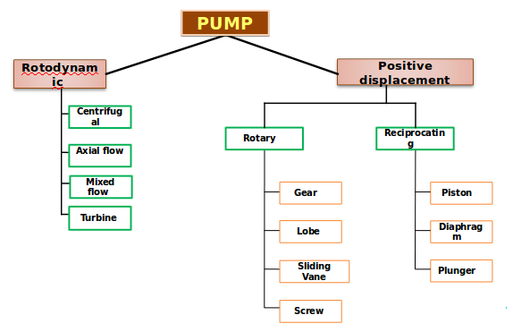
Ans- Pump is a device/machine which provides energy to a fluid in a fluid system by converting mechanical energy supplied to hydraulic energy and transfer it to liquid flowing through a pipe. On the basis of the way mechanical energy is converted to hydraulic energy, pumps are classified as:
1)Rotodynamic / Kinetic pump.
2)Positive displacement
They can be further classified into:
pump?

Working of centrifugal pump

Like any other pump, centrifugal pump also converts the rotational energy from prime mover to moving fluid during which a portion of energy add up to kinetic energy of the fluid. The fluid enters axially to the eye of the impeller under atmospheric pressure. The centrifugal energy exerted on the fluid by the impeller moves the flow away from the eye of the impeller through impeller vanes to the walls of the volute casing and get out through the discharge port. Fluid is drawn continuously into the pump due to the pressure drop in the pump.The volute is designed and manufactured such that it is wider at the discharge, which leads to increase in viscosity when fluid strikes on them. This specific shape helps liquid/fluid to expand leading to slow flow due to which the kinetic energy get converted to pressure energy. As it is said "Energy can neither be created nor destroyed but only be changed". This generated pressure then forces the liquid out of pump discharge.

Main difference between Kinetic/Rotodynamic pumps and Positive displacement pump 

The main difference between the kinetic and positive displacement pump depends on the method of fluid transfer. Rotodynamic pumps on one hand gives kinetic energy to the fluid and then convert it to pressure energy during discharge through the pump. On other hand a positive displacement pump moves a fixed amount of fluid / liquid within the pump by applying mechanical force to boundaries containing fluid volume.

Difference between centrifugal pump and reciprocating pump:

Source for creating below table: (https://www.slideshare.net/506314/pump-46519851)

Parameter Centrifugal Pumps Reciprocating Pumps
Optimum Flow and Pressure Applications Medium/High Capacity,Low/Medium Pressure Low Capacity,High Pressure
Maximum Flow Rate 100,000+ GPM 10,000+ GPM
Low Flow Rate Capability No Yes
Maximum Pressure 6,000+ PSI 100,000+ PSI
Requires Relief Valve No Yes
Smooth or Pulsating Flow Smooth Pulsating
Variable or Constant Flow Variable Constant
Self-priming No Yes
Space Considerations Requires Less Space Requires More Space
Costs Lower Initial
Lower Maintenance
Higher Power
Higher Initial
Higher Maintenance
Lower Power
Fluid Handling Suitable for a wide range including clean,
non-abrasive fluids to fluids with abrasive,
high-solid content. Not suitable for high viscosity fluids,
Lower tolerance for entrained gases
Suitable for clean, clear, non-abrasive fluids.,
Specially-fitted pumps suitable for abrasive-slurry service.
Suitable for high viscosity fluids,
Higher tolerance for entrained gases

Q.How is head developed by an Impeller?
Out of the two main components, impeller and diffuser/volute/vortex the impeller takes power from the rotating shaft and accelerate the fluid and the diffuser transform the high velocity kinetic energy into pressure.
True velocity profile of fluid inside an impeller

velocity at the inlet and outlet of impeller.

velocity at one paint on the impeller blade

Based on free body diagram
The mass of the segment:

The centrifugal force acting on this elementary mass would be:

The pressure increase due to action of centrifugal pump:

Integrating the equation between intake and discharge:

In terms of head:

In practice the potential head is not only due to the centrifugal force but also due to the change in relative velocity of the fluid inside the impeller. Hence:

For one stage of an ESP, The total head is due to the sum of potential head and velocity head. Thus theoretical head can be calculated as:


Moment equation:

Total pressure loss along the streamline:
If the fluid is inviscid; No change of velocity in z and  (symmetric velocity) direction; Neglect the pressure drop due to gravity:
Therefore, the total pressure losses along the streamline can be express as:


From the triangle geometric relationship:

Hence:

Simplifying this equation gives


Finally, the pressure difference across a streamline is given:

Integrate this equation gives the pressure increase across one stage:

By definition:
 
Hence:

Using the geometrical relationships:

This equation can be expressed as the Euler Equation:

Field unit:


Construction of centrifugal pump


Casing: This part performs the function of converting the kinetic energy into pressure energy. This is of three main types:

Volute casing (For high head): It is a curved funnel with advance in area as it reach the discharge port. This reduces the flow rate and so increases the pressure of the fluid.

Circular casing (For low head and high capacity):These have stationary diffusion vanes surrounding the impeller periphery such that they convert kinetic energy to pressure energy . Conventionally they are used in multi-stage pump.

Vortex casing:A circular chamber is introduced between casing and impeller-increasing the efficiency of the pump.

Impeller: It is the main rotating part that provides the centrifugal acceleration to the fluid. There are mainly three types of impeller used in the centrifugal pump:
1)Open Impeller: Vanes are cast-free on both sides.
2)Semi-Open Impeller: Vanes are free cast on one side and enclosed on other.
3)Enclosed Impeller: Vanes are located between the two discs in one single casing.

Shaft:It acts as a transmitter of torque during start and operation of pump. It also support Impeller and other rotating parts of pump.

Net positive suction head(NPSH)

In a hydraulic fluid pump system, NPSH is the minimum head required to avoid cavitation due to flashing of fluid as low presure at suction side leads to cavitation. During operation of pump if the presure at the suction drops below the vapour presure of fluid, fluid start to boil forming bubble at high presure and brust when they reach low presure leading to severe cavitation damage to the impeller blade and sudden impulsive shocks. This fact puts a limit to the maximum suction head a pump can had.

NPSH can be defined as:

Where, Pv is the vapour pressure and V is speed of water at suction side.

Classification of centrifugal pump

Centrifugal pumps may be classified according to:

1)Working Head: Centrifugal pumps are classified into low(15m), medium(15-45m), High speed pump(more than 45m).
2)Specific Speed
3)Types of casing: Centrifugal pumps can be divided into following type based on casing; Volute, Vortex and diffuser.
Image credit: www.educationdiscussion.com

4)Direction of flow of water: Centrifugal pumps can also be classified according to the type of flow as under:
  • Radial flow: It is a type of flow in which the flow in the impeller is radial direction. They are generally used when requirements are high at low discharge.
  • Mixed flow: It is a type of flow in which the flow is mixture of radial and axial increasing the area of flow. Then they are used where discharge and head requirement are medium.
  • Axial flow:These pumps find their use where discharge is high at low head such as in the case of irrigation.

Diffrent impeller Types

5)Number of entrance to impeller: Centrifugal pumps can have either single or double entrance according to the discharge needed.
6)Number of stages: A centrifugal pump can have a single stage with a impeller key to the shaft or it can be a multi stage pump. A multi stage pump has a no of impellers mounted on the same shaft and enclosed in the same casing.

Advantages and disadvantages of centrifugal pump

Advantage:
1)Very high flow rate
2)Low maintenance
3)Continuous flow
4) cost of installation and size does not affect the performance at any cost.

Disadvantage:
1)Pressure generated by pump is less compared to positive displacement pump.
2)Need priming before start.

Centrifugal pump Characteristic Curves

Pump performance:
Brake horse power and capacity:
 NPSH and capacity: The curves show the relationship between the capacity by which the pump will deliver and the NPSH, which is required for proper operation of pump at that capacity. Lack of NPSH will lead the pump to run improperly and cause cavitation.
#Cover Image Credit: www.pumpsandsystems.com

# Too many books, study material,ppt notes and other online sources has been refereed prior to writing this article but no part is copied or produced  from any of the source except for the one little part which is clearly mentioned with site/source link, but explained same thing in better detailed way.

Author: Amit                                                                                      Article Requested by: Deepak Kumar

If you have any complain regarding the post please do contact us!