Overhaul and Repair of a Marine Turbocharger


Introduction
The turbocharger is a very sensitive device; It must be treated with caution. It is very important to know the detailed step by step, to disassemble and in this article we will discuss some safety measures that must be taken before and during the dismantling process.
A turbocharger has a turbine on one side and a compressor on the other. The disassembly should always keep the compressor side beginning to measure the critical clearance between the mounting of the cover on the compressor side and the compressor side tree. This is a very important area that needs to be met and must be supported as he left.

THE MAKER’S MANUAL MUST BE READ AND UNDERSTOOD BEFORE ANY WORK IS UNDERTAKEN ON ANY MACHINERY.

Safety while Dismantling the Turbocharger

Inform the operating personnel accordingly before starting any maintenance work on turbocharger.
As a precaution, place a receptacle for leaking oil under the turbocharger.
Before starting work, secure the rotor against turning.
Ensure that absorbent material is available to soak up any spilled oil.
Ensure that operation and process materials are drained, collected, and disposed of in a safe manner.
Ensure that all spares and tools are available for dismantling and assembling.
Dismantled safety devices must be reassembled and subjected to a functional test immediately after conclusion of maintenance and repair.

Turbocharger Overhauling


 Turbocharger Overhauling

Tools Required for Dismantling

Open and ring spanner
Box spanner
Claw spanner
Tommy spanner
Bearing pushing tool
Bearing pulling tool
Pump disc locking plate
Pump removing tool set (provided by manufacturer)
Impeller removing tool set (provided by manufacturer )
Shaft pushing tool
Clearance measuring instruments
Screw driver

Preliminaries before Dismantling:

Before dismantling, exhaust gas from the turbine should be bypassed and a blanking plate should be fitted in turbine inlet casing.
Drain the lube oil from the built-in sump.
Remove the turbine side cooling water connection and drain all water

Turbocharger Sectional View


Turbocharger Sectional View
Image credit:www.auto-innovations.com

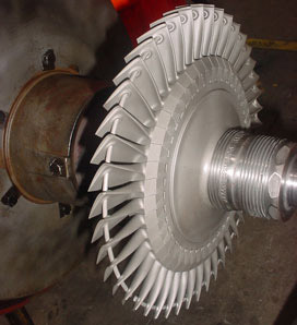
Turbine and Impeller

Image credit: www.romaga.com

Turbocharger Dismantling Procedure

Compressor Side Removal:
Dismantling should always be started from the compressor side.
1) First remove the filter silencer assembly or compressor inlet casing from position.
2) Remove the compressor end cover and drain plug on the compressor side.
3) Remove the suction cover and measure the critical clearance .It is the distance between the compressor end cover mounting face and shaft end .Mark it as K.
4) Pull the rotor shaft towards the compressor side until the impeller comes in contact with the insert and determine K2.
1. Impeller clearance L = K - K2
5) Thrust the rotor shaft towards the turbine side until the turbine disc and nozzle ring comes in contact with each other and measure K1
2. Disc clearance M = K1 - K
6) The above measured clearance is very important as this will determine the proper functioning of the labyrinth seal between the impeller and exhaust shield and also the alignment of the shaft.
7) Remove the lube oil pump assembly after removing the pump locking plate.
8) Remove the bearing nut and bearing nut washer.
9) Fix the bearing pulling tool in position and slowly tighten it. This will pull the ball bearing assembly out. Care should be taken while removing bearing to avoid any damage to the bearing and rotor shaft end threads.
10) Mark the position of the bearing in position to put it back as it is while assembling.
11) The ball bearing assembly should not be disturbed in any case. If it is damaged, the whole assembly should be replaced with the manufacturer's new part.
12) Now remove the compressor outlet casing with diffuser.
13) Remove the impeller nut and impeller washer.
14) Remove the impeller and inducer from position.

Turbocharger turbine side dismantling procedure for overhauling,for repairing damaged turbine blades, for cleaning cooling water spaces is detailed in the second page of the article "Overhaul and Repair of a Marine Turbocharger."
Turbine Side Removal
1) Remove the turbine end cover with sight glass on the turbine side.
2) Measure the clearance between the turbine end cover mounting face and shaft end.
3) Check the axial deflection of the pump disc cover. The permissible axial deflection of the pump cover is 0.05 mm.
4) Check the rotor shaft by turning by hand.
5) Remove the pump disc locking plate.
6) Loosen the lube oil disc cover and pump washer on the lube oil pump disc by removing the bolt.
7) Remove the outer shaft end nut and tab washer and then remove inner shaft end nut.
8) Remove the lube oil disc from position.
9) Loosen the bearing nut and bearing nut washer and remove from place.
10) Fix the bearing pulling tool on a resilient mounting and slowly tighten it, and this will pull the roller bearing on turbine side slowly out.
11) Care should be taken while removing the bearing to avoid damage to the shaft outer end threads and bearing.
12) Do not disturb the bearing assembly as improper bearing position may misalign the rotor shaft.
13) Before removing, put punch mark on the bearing in position so that it can be put back as it is.
14) Remove the turbine inlet casing from the turbine outlet casing.
15) Now the whole rotor shaft can be pulled out from the compressor side. While pulling out the shaft, care must be taken to avoid damage to the turbine blades and labyrinth sealing arrangements on the shaft.
16) Remove tab washer and remove seal plate to the turbine outlet casing.
17) Remove shroud ring and shaft seal from the turbine outlet casing.
18) Remove nozzle ring assembly from the turbine inlet casing.
Finally remove the air seal adjusting screw, anti-corrosion zinc assembly, sand cover, and other various accessories in position

# Various books, study material and other online sources has been refereed prior to writing this article but no part is copied or produced  from any of the source but explained same thing in better detailed way.

Author Amit                                                                     

If you have any problem with the content contact us! we will act ASAP


Watch Keeping at sea for Marine Engineers | Step-by-step


Watch keeping is an integral part of marine engineer’s duties on board ship. The technicians perform tasks and routines for monitoring the ship's engine room. The clocks are divided into three periods of four hours and the following work must be carried out and checks carried out at sea.

  • Check the colour of  exhaust emission from funnel.
  • Check the Economizer temperatures, pressure drop and the system for any leakage.
  • Check the oil fired boiler water level, blow through gauge glass and check pressure.
  • Check the boiler circulating pump for operating pressure, vibration, noise, gland leakage and bearing oil level.
  • Check and confirm normal operation of incinerator if running.
  • Check the waste oil tank level and temperature, drain off water.
  • Check Main & Aux. engine header tank levels, if they require filling record the quantity of water added.
  • Check the temperatures and pressure of the fuel valve cooling system. Examine the level of the F. V. C  header tank, check for contamination and confirm through flow.
  • Check stern tube header tank level, return flow, sump, pump and oil condition.Examine M. E cylinder tops for leakage, movement, overheating and any temperature or pressure outside the normal parameters.
  • Check for exhaust gas leaks.Examine turbo charger oil levels, pump operation, temperatures, pressures and differentials, whilst checking also for any unusual noise or vibration.
  • Monitor air cooler pressure drop, and ensure Makers operating parameters are adhered to with regard to dew point temperature.
  • Check cylinder oil day tank level and individual lubricators for level, flow and function.
  • Check all bunker fuel tanks for level, temperature and drain for water.
  • Check fuel fine filter differential.Examine fuel pumps for leakage or unusual noises.Ensure oil mist detector is functioning correctly and test alarm.
  • Check ME governor oil level and fuel pump racks.
  • Examine auxiliary blower if running and scavenge belt to ensure that scavenge and air cooler drains are clear.
  • Feel over scavenge belt.Test air line drains for water.
  • Check all standby pumps are on auto mode and ready to start.
  • Check air compressor  oil level, and the temperatures and pressures whilst  running.
  • Check fresh water generator for normal operation & also chemical dosing to feed line.
  • Check sewage treatment plant for normal operation.
  • Examine A/E and check all running parameters are within limits. Fuel leakage, non fitting of double skin pipes and removed  protection or insulation from exhaust manifolds to be rectified immediately .
  • Check A/E bilge’s for leakage.
  • Confirm that an alternator engine is on standby in the control room and that the L. O priming pumps are on Auto.
  • Checking drinking and domestic water hydrophore systems for levels, and leakage. Ensure that the Calorifier, circulating pump and UV Sterilizer are operating satisfactorily.
  • Examine boiler feed water system for normal pump operation and check the cascade tank for temperature and level. Also check that there is no hot well contamination with fuel oil due fuel oil heating coil leaks.
  • Examine air reservoirs and check the drains for water, ensure that control and service air reducing valves are functioning correctly and that the control air dehydrator is operating normally.
  • Examine the purifier room for leakage, ensure that running purifiers and operating normally with regard to oil levels, flow rates, temperatures and pressures. 
  • Ensure lowest throughput for L O purifiers.Check Calorifier.
  • Examine Booster pumps, flow-meter and heaters for normal operation without leakage.
  • Ensure that all main engine pumps are running normally and that standby pumps are ready for Auto operation.
  • Check HFO Serv & Sett tanks levels and temp. Drain off water.
  • Check all running purifiers for normal operation. Check gear case oil level, Separated Oil temperature and feed rate, motor load etc.
  • Skim off sludge from recycle tank.
  • Check F. O booster p/p, check F. O temperature.
  • Check JCW pump and motor for normal operation.
  • Check M/E Lubricating Oil Pressure (Bearing), X-Head Oil Pressure and Piston Cooling.Check piston cooler and L. O cooler in/out temp.
  • Check sounding of all sludge tanks, bilge storage tanks, compare with previous sounding.
  • Check M/E L O pump discharge filter Pressure drop.
  • Check M/E L O pump/motor for normal operation.
  • Check thrust bearing L. O temperature Fwd/Aft.
  • Check E/R bilge level with special attention under the flywheel.
  • Check L. O levels and temps of intermediate shaft bearings.
  • Check stern tube L. O sump level, oil pressure, temp and return flow.
  • Check M/E L. O sump sounding. compare with earlier soundings recorded.
  • Check and confirm L. O purifier is operating normally note L. O temperature.
  • Check piston cool leak off tank, open skimming v/v to skim off oil from top.
  • Check piston cooling water tank level top up if required.
  • Check and confirm main S. W p/p, motor and auxiliary  S. W pump/motor working normally.
  • Check piston cooling p/p pressure and in/out temp of all units check flow.
  • Check A/E load and winding temp. Do a function test on alarm panel. Reconfirm all running parameters of M/E and A/E.
  • See the Chief Engineer’s standing instruction book and also notice board for daily instruction and guidance. Discuss with outgoing watch keeping engineer if there have been any special operations problems during his watch or any change in status of running machinery Function and lamp test of Alarm panel.
  • Check no alarms are inhibited.Ensure no alarms indicating abnormal condition are active.
  • Ensure air and water on deck shut if not required.
  • Log down all parameters in log book
  • Check for following hazards and rectify :-
  • No Fuel, L. O or water  leaks.
  • No loosely stowed equipment.
  • Gas bottles shut and welding plant shut down.
  • Fuel high pressure pipes for M/E & A /E’s secure and no leaks.
  • No abnormal vibrations of any type.
  • No water tight openings open unnecessary.
  • Ensure that the welding equipment is off.Double check additional A/E on standby, and Emergency Generator on Auto.
  • Double check M. E controls on Bridge and max speed limit set as per Chief Engineer’s instructions
  • Check no alarms have been isolated, unless authorized by C/E and E/O. Note there are no existing alarm condition, unless a valid reason and C/E and E/O aware of.
WHEN IN DOUBT DO NOT HESITATE TO CALL CHIEF ENGINEER


Author Amit                                                                            


TURBOCHARGERS & ITS SURGING

Turbocharger sketch
Turbocharger
Shown in the sketch is a section of turbocharger fitted on a large 2 stroke engine. It consists of a single stage, axial flow exhaust gas driven turbine mounted on a common shaft with centrifugal air compressor.

Turbine : The exhaust gas enters through the nozzle ring and is then directed to the turbine rotor blades at high velocity. The nozzle ring converts the energy in the exhaust gas to kinetic energy. The turbine blades are firmly fitted on the wheel by fir tree shaped roots which give positive fixing and minimum stress concentration.
The blades are held together at the free end by lace wire to dampen vibration. The nozzle ring, turbine wheel, blades and rotor shaft are manufactured from heat resisting nickel chrome alloy steel to withstand high working temperatures. The turbine casing is of cast iron with adequate water cooling spaces. In modern slow speed 2 stroke engines with relatively low exhaust gas temperatures the casings are un-cooled.

Blower : The air blower casing is fitted with filters and silencers at the air inlet of the casing. A inducer is fitted just before the impeller to direct the flow of air to the centre of the impeller without any shock. The impeller is made of light aluminum alloy. The impeller takes in air axially and delivers it radially through a diffuser to the volute casing. The kinetic energy is converted into pressure energy and air is delivered to the air cooler for cooling and then to scavenge manifold. Compressor casing is of cast aluminum and un-cooled.

Labyrinth Seals
: Two labyrinth seals are fitted to the shaft, one between thrust bearing and air compressor and the other between turbine and bearing. They are sealed with air under pressure from the compressor discharge through internal passages. The seals prevent possible oil leakage into the turbine and compressor and also prevent exhaust gas leakages into bearing oil.

Bearings : Two shaft bearings are fitted, one at each end. End thrust is taken at the compressor bearing, allowing the turbine bearing free thermal expansion of the shaft. Bearings may be of either plain sleeve types with copper lead bushes on hardened steel sleeves or ball and roller type.

Lubrication : Ball and roller bearings may be lubricated by self contained gear type pumps operated from the shaft and drawing oil directly from the independent bearing sump.
For sleeve type bearings either the lubricating oil from engine lubrication system is used or a complete different system can be used exclusively for the turbochargers. In which case additional pumps, motors, filters and cooler will be required.

Maintenance on Turbochargers :
  • Regular checking of oil level in bearing sump and changing oil after 1000 hrs
  • Cleaning of air filter after 1000 hrs
  • Renewal of bearings after 16000 hrs and gear pumps to be renewed or reconditioned after 16000 hrs
  • The cooling water chamber to be cleaned at every 8000 hrs.
  • Regular water washing of compressor and turbine.

Water washing of Turbocharger compresso
Water washing of Turbocharger compressor
Turbocharger  Cleaning : Under operating conditions turbocharger systems may become fouled, causing reduced efficiency, loss in power and surging.
Compressor :
Oil mist and dust drawn from engine room may get deposited on the compressor surface.  Dirt deposits should be dislodged by injection of water during operation.
A small container is provided which is filled with water to clean the compressor. Water is injected using air from the compressor. Cleaning is carried at full load and performed once every day.
1.  Open filler of the tank and fill with fresh water. Close vent.
2.  Open air supply valve A
3.  Open injection valve B and wait for 30 seconds.
4.  Close valve A and B and open vent.
5.  Check to ensure tank is empty.

Turbine :

Fouling of the turbine can occur due to products from combustion of fuel, ash and any other non-combustibles present in the fuel.
Water Washing of Turbine side: The dirt deposits on turbine side can be reduced by periodic cleaning (water washing) during operation. Dirty turbines lead to higher temperatures of exhaust gas and higher stresses on bearings due to imbalance.

  • The engine speed must be reduced to reduce the exhaust temperature and prevent thermal shock of the turbine.
  • Once the exhaust temperature is at or below the manufacturer's limit, the turbocharger drain can be opened and freshwater admitted to the turbine casing.
  • Water should be admitted slowly until water appears at the drain, then the water flow can be increased.
  • Water supply and drain to be closed once fairly clean water starts flowing from the drain.
  • After the cleaning is completed the engine must be run on same speed for about 5 mins until all parts are dry.
  • This operation is usually carried out on a weekly basis.
Arrangement for turbine water-washing
Dry Cleaning : The turbocharger speed does not have to be reduced when dry cleaning. A container is filled with correct amount of cleaning material, either ground nutshells or small grains of rice. The valve from the container is then opened to blow the material into the turbine casing. This is carried out normally every two days.

New series of two-stage turbochargers :

Two-stage turbocharging is important for the development of new generation of large-bore diesel engines with reduced exhaust emissions. Reducing engine emissions through internal measures is achieved by increasing the mean effective pressure. This requires high charge-air pressures but cannot be achieved through single-stage turbocharging. Two-stage turbocharging enables the charge-air pressure to be increased substantially while simultaneously reducing exhaust emissions, despite the increased specific engine output. MAN Diesel & Turbo has introduced  two-stage turbocharging to the market with its TCX series.
Two-stage turbocharging systems consist of two turbochargers of different size connected in series. The exhaust gas coming from the engine drives the turbine of the smaller, high-pressure turbocharger (the first stage) which in turn drives the turbine of the larger, low-pressure turbocharger (the second stage).
The low-pressure turbocharger's compressor draws in ambient air and sends it via an intermediate cooler to the high-pressure turbocharger's compressor. Here, the air is compressed once again and, via a further charge-air cooler, sent to the engine. The system adapts to varying operating conditions either through controlled turbine bypass or by variable nozzle rings (VTA).
VTA – Variable Turbine Area, allows charge air delivery to be optimized by using adjustable vanes. By altering the pitch of the adjustable vanes, the exhaust gas pressure is regulated and thus the air amount can be precisely matched to the quantity of injected fuel at all points in an engine’s load and speed range. The result is reduced specific fuel consumption, reduced emissions HC and CO2 and improved engine response.
Although two stage turbocharging is more efficient than single stage, the additional cost and complexity of the system makes it generally unpopular.

Surging
Surging is a phenomenon that affects centrifugal compressor when the mass flow rate of air falls below a sustainable level for a given pressure ratio.
Surging is a condition whereby an imbalance in demand and supply of air from the turbocharger causes a rapid deceleration. When this occurs the pressure downstream of the compressor is relieved to atmosphere backwards through compressor. This is known as surging and it is accompanied by a loud barking noise and vibration. It was not uncommon on pulse systems in heavy weather, it is less prevalent in modern constant pressure designs.
The turbocharger must produce the required scavenge pressure. When the turbocharger cannot maintain pressure and the air flow decreases, the delivered pressure falls below the scavenge pressure which results in reversal flow and surging occurs.
If surging occurs engine speed must be reduced, the compressor should be water washed and air filters cleaned. If this does not solve problems the engine balance should be checked by taking set of indicator cards.
Conditions leading to Surging: 
Surging may occur in heavy weather when propeller comes out of water and governor shuts the fuel almost instantaneously.
Some possible reasons of surging are :
  • For multi blower installations surging can occur due to a difference in maintenance of cleaning causing one or more to operate at pressure ratio's above its capability
  • When governor shuts fuel instantaneously.
  • change in engine speed/ load relationship- say due to hull fouling
  • cylinder power imbalance
  • faulty injectors or timing
  • dirty air filter
  • dirty air cooler (air side)
  • dirty turbine nozzle ring
  • deposits on blades or impeller
  • damage to blades
It is also possible that components downstream from the blower exhaust such as a fouled exhaust gas boiler can also lead to surging


Author marineGuru