Centrifugal pump is a machine used to convert mechanical energy into
pressure energy by utilizing centrifugal forces with radical outward
flow. It is the most common type of pump used world wide for various
section such as agricultural, sewage, power generation and shipping. It
is a subcategory of kinetic pumps and based on the principle of forward
vertex flow, which states that when a fluid of certain mass is rotated
by external torque, there is a sudden rise in pressure head.
Centrifugal
pumps are used world wide to handle liquid of low viscosity. Talking
about shipping they comprises for more than 60% of total fluid handle
and pumps on ship. Rather its working is too simple. It consists of two
main components, the diffuser or volute and the impeller. The impeller
is the one which rotate converting driver energy to kinetic energy and
the volute remain stationary converting the kinetic energy to pressure
energy.
Centrifugal pumps are rather unique as they can
pump at very high flow rate and even can be throttled. The answers to
these lies to the shaft driven impeller rotating at a speed of 1750 to
3500 rpm inside the casing. The liquid flows to the suction port and
then leave out of the discharge port of the volute casing at pressure
heat with the same flow rate.
But let get back to the basics;
Q.What is a pump?
Ans-
Pump is a device/machine which provides energy to a fluid in a fluid
system by converting mechanical energy supplied to hydraulic energy and
transfer it to liquid flowing through a pipe. On the basis of the way
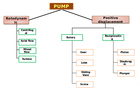
mechanical energy is converted to hydraulic energy, pumps are classified
as:
1)Rotodynamic / Kinetic pump.
2)Positive displacement
They can be further classified into:
Working of centrifugal pump
Like
any other pump, centrifugal pump also converts the rotational energy
from prime mover to moving fluid during which a portion of energy add up to kinetic energy of the fluid. The fluid enters axially to the eye of
the impeller under atmospheric pressure. The centrifugal energy exerted
on the fluid by the impeller moves the flow away from the eye of the
impeller through impeller vanes to the walls of the volute casing and
get out through the discharge port. Fluid is drawn continuously into the
pump due to the pressure drop in the pump.The volute is designed and
manufactured such that it is wider at the discharge, which leads to
increase in viscosity when fluid strikes on them. This specific shape
helps liquid/fluid to expand leading to slow flow due to which the
kinetic energy get converted to pressure energy. As it is said "Energy
can neither be created nor destroyed but only be changed". This generated pressure then forces the liquid out of pump discharge.
Main difference between Kinetic/Rotodynamic pumps and Positive displacement pump
The
main difference between the kinetic and positive displacement pump
depends on the method of fluid transfer. Rotodynamic pumps on one hand
gives kinetic energy to the fluid and then convert it to pressure energy
during discharge through the pump. On other hand a positive displacement
pump moves a fixed amount of fluid / liquid within the pump by applying
mechanical force to boundaries containing fluid volume.
Difference between centrifugal pump and reciprocating pump:
| Parameter |
Centrifugal Pumps |
Reciprocating Pumps |
| Optimum Flow and Pressure Applications |
Medium/High Capacity,Low/Medium Pressure |
Low Capacity,High Pressure |
| Maximum Flow Rate |
100,000+ GPM |
10,000+ GPM |
| Low Flow Rate Capability |
No |
Yes |
| Maximum Pressure |
6,000+ PSI |
100,000+ PSI |
| Requires Relief Valve |
No |
Yes |
| Smooth or Pulsating Flow |
Smooth |
Pulsating |
| Variable or Constant Flow |
Variable |
Constant |
| Self-priming |
No |
Yes |
| Space Considerations |
Requires Less Space |
Requires More Space |
| Costs |
Lower Initial
Lower Maintenance
Higher Power |
Higher Initial
Higher Maintenance
Lower Power |
| Fluid Handling |
Suitable for a wide range including clean,
non-abrasive fluids to fluids with abrasive,
high-solid content. Not suitable for high viscosity fluids,
Lower tolerance for entrained gases |
Suitable for clean, clear, non-abrasive fluids.,
Specially-fitted pumps suitable for abrasive-slurry service.
Suitable for high viscosity fluids,
Higher tolerance for entrained gases |
Q.How is head developed by an Impeller?
Out
of the two main components, impeller and diffuser/volute/vortex the
impeller takes power from the rotating shaft and accelerate the fluid
and the diffuser transform the high velocity kinetic energy into pressure.
True velocity profile of fluid inside an impeller
velocity at the inlet and outlet of impeller.
velocity at one paint on the impeller blade
Based on free body diagram
The mass of the segment:

The centrifugal force acting on this elementary mass would be:

The pressure increase due to action of centrifugal pump:

Integrating the equation between intake and discharge:

In terms of head:

In practice the potential head is not only due to the centrifugal force but also due to the change in relative velocity of the fluid inside the impeller. Hence:

For one stage of an ESP, The total head is due to the sum of potential head and velocity head. Thus theoretical head can be calculated as:

 Moment equation:
Total pressure loss along the streamline:
Moment equation:
Total pressure loss along the streamline:
If the fluid is inviscid; No change of velocity in z and (symmetric velocity) direction; Neglect the pressure drop due to gravity:
Therefore, the total pressure losses along the streamline can be express as:


From the triangle geometric relationship:

Hence:

Simplifying this equation gives


Finally, the pressure difference across a streamline is given:

Integrate this equation gives the pressure increase across one stage:

By definition:

Hence:

Using the geometrical relationships:

This equation can be expressed as the Euler Equation:

Field unit:

Construction of centrifugal pump
 Casing
: This part performs the function of converting the kinetic energy into pressure energy. This is of three main types:
Volute
casing (For high head): It is a curved funnel with advance in area as
it reach the discharge port. This reduces the flow rate and so increases
the pressure of the fluid.
Circular casing (For low
head and high capacity):These have stationary diffusion vanes
surrounding the impeller periphery such that they convert kinetic energy
to pressure energy . Conventionally they are used in multi-stage pump.
Vortex casing:A circular chamber is introduced between casing and impeller-increasing the efficiency of the pump.
Impeller:
It is the main rotating part that provides the centrifugal acceleration
to the fluid. There are mainly three types of impeller used in the
centrifugal pump:
1)Open Impeller: Vanes are cast-free on both sides.
2)Semi-Open Impeller: Vanes are free cast on one side and enclosed on other.
3)Enclosed Impeller: Vanes are located between the two discs in one single casing.
Shaft:It
acts as a transmitter of torque during start and operation of pump. It
also support Impeller and other rotating parts of pump.
Net
positive suction head(NPSH)
In a hydraulic fluid pump system, NPSH is
the minimum head required to avoid cavitation due to flashing of fluid
as low presure at suction side leads to cavitation. During operation of
pump if the presure at the suction drops below the vapour presure of
fluid, fluid start to boil forming bubble at high presure and brust when
they reach low presure leading to severe cavitation damage to the
impeller blade and sudden impulsive shocks. This fact puts a limit to
the maximum suction head a pump can had.
NPSH can be defined as:
Where, Pv is the vapour pressure and V is speed of water at suction side.
Classification of centrifugal pump
Centrifugal pumps may be classified according to:
1)Working Head: Centrifugal pumps are classified into low(15m), medium(15-45m), High speed pump(more than 45m).
2)Specific Speed
3)Types of casing: Centrifugal pumps can be divided into following type based on casing; Volute, Vortex and diffuser.
 |
| Image credit: www.educationdiscussion.com |
4)Direction of flow of water: Centrifugal pumps can also be classified according to the type of flow as under:
- Radial
flow: It is a type of flow in which the flow in the impeller is radial
direction. They are generally used when requirements are high at low
discharge.
- Mixed flow: It is a type of flow in which the flow is
mixture of radial and axial increasing the area of flow. Then they are
used where discharge and head requirement are medium.
- Axial flow:These pumps find their use where discharge is high at low head such as in the case of irrigation.
5)Number of entrance to impeller: Centrifugal pumps can have either single or double entrance according to the discharge needed.
6)Number
of stages: A centrifugal pump can have a single stage with a impeller
key to the shaft or it can be a multi stage pump. A multi stage pump has
a no of impellers mounted on the same shaft and enclosed in the same
casing.
Advantages and disadvantages of centrifugal pump
Advantage:
1)Very high flow rate
2)Low maintenance
3)Continuous flow
4) cost of installation and size does not affect the performance at any cost.
Disadvantage:
1)Pressure generated by pump is less compared to positive displacement pump.
2)Need priming before start.
Centrifugal pump Characteristic Curves
Pump performance:
Brake horse power and capacity:
NPSH
and capacity: The curves show the relationship between the capacity by
which the pump will deliver and the NPSH, which is required for proper
operation of pump at that capacity. Lack of NPSH will lead the pump to
run improperly and cause cavitation.
#Cover Image Credit: www.pumpsandsystems.com
# Too many books, study material,ppt notes and other online sources has been
refereed prior to writing this article but no part is copied or
produced from any of the source except for the one little part which is clearly mentioned with site/source link, but explained same thing in better
detailed way.
Author
: Amit Article Requested by: Deepak Kumar
If you have any complain regarding the post please do contact us!




 Posts
Posts

