How to apply for marine engineering | Admission


A Naval/Marine engineer has too many tasks and duties to take over. A marine engineer has all the functions and marine engines to check. In short, a naval engineer is a person who deals with everything related to the ship, from small things to big issues. Now the responsibility of ship engineers is not only related to ships, but also must ensure the safety of the crew and sailors.

Being A marine engineer is a lucrative job offer. A marine engineer acquires considerable knowledge and the ability to work under pressure and difficult conditions at sea. They are the true saints with jack of all trades and an ace of diesel engines. Working in  the transport company makes them meet and see many universal things as well as exposure to the outside world. They know how the configurations of the nations of the world are the same. They know how to get at different places in the world "Things Done". They look like the experts end their work quietly making the wheels of the global economic race.  


About the course: -

Marine Engineering is a 4 year regular course in various colleges in India specially situated in coastal areas. For four years of maritime engineering, B.Tech has been a course of proficiency in naval/Marine engineer officer class IV, issued by the Directorate-General for Shipping, Government of India, after six months of maritime service, the cadets will sail marine engineers worldwide on board Trade. This course is strictly residential.


Eligibility criteria to apply for marine engineering:

The Eligibility criteria for admission to B.Tech (Marine Engineering) :

Academic Qualifications: The candidate must have successfully completed the Senior Secondary Examination (10+2) or its equivalent with :
i)  At least 60% marks in Physics, Chemistry and Mathematics (PCM) and
ii) At least 50% marks in English either in Class X or Class XII.

Age: Candidates  less than 25 years of age as on 1st of August in the year of admission will be eligible to apply. The date of birth as recorded on the applicants School Leaving Certificate will be considered for this purpose.
* The Upper age limit for admission relaxed for SC/ST candidates by 5 Years.

Marital Status: Only Unmarried candidates will be considered.
Physical and Medical Standards : Medically fit as per the standards set by Merchant Shipping Medical Examination Rules, 2000 as
amended from time to time.

Eye-sight :
Distance vision (unaided) 0.5 (values given in Snellen Decimal Notation) (6/12) in each eye or 0.67 (values given in Snellen Decimal Notation). (6/9) in better eye and 0.33 (Values given in Snellen Decimal Notation) and (6/18) in other eye. Normal colour vision.
Admission Procedure:
Through online / off-line examination, Interviews, Psychometric Test, And Medical Test.
The Entrance test format is multiple choice type. Candidates can be asked questions related to their 10-12th education, general English, etc. Selected applicants will be invited to a personal interview and later to psychometric test to assess their psychology including their suitability for a career In the sea. The selected candidates will be sent for medical examination. The final selection is obtained based on the ratio after the medical examination.


Some best Marine Engineering Colleges in the Country:

India is home to some of the oldest and at the same time the best institutes for studying nautical architecture, Marine engineering and science. Affiliates to the respective universities, colleges and courses, which are approved by the National Accreditation Board (NBA) and the Technical Education Council of India (AICTE).

A few of the best are:
  1. Tolani Maritime Institute (TMI),Mumbai.
  2. International Maritime Institute, Noida.
  3. Vels Academy of Maritime studies, Chennai.
  4. Maharashtra Academy of Naval Education and Training (MANET), Pune.
  5. International Maritime Institute (IMI), Delhi.
  6. International Maritime Academy (IMA), Chennai.
  7. Institute of Technology and Marine Engineering (ITME), Kolkata.
  8. Coimbatore Marine College (CMC).
  9. Samundra Institute of Marine studies, Mumbai.
  10. Academy of Maritime Education and Training (AMET).
Other best international college:

Hard to get a job as TME or Deck Cadet ? | Getting started on job hunt


For the past few years, I have been noticing how difficult it has been to get a job as trainee marine engineer or deck cadet on ship after completing marine engineering or nautical science course even from a well recognised maritime institute. The main reason behind this would be the approval of so many substandard institutions by the government in recent years, because of which the number of students graduating every year is far more than the number of job openings that we have. Along with this, a lot of job agents, mostly fraud ones have come up offering jobs in known and unknown companies taking a huge amount of money and you would wonder that the average agent fee they are charging has been above 3.5 to 4 lakh INR for a normal company and 5 to 6 lakh INR for a well known highly paying company which is one third of actual engineering course fee itself. The funniest part in fact is that the agents get only 10 to 15 % of the fee and the rest goes to the people who are sitting on top of crewing department in these companies, even the best shipping companies I would say.Though it is rare that the companies take freshers from outside without reference, there are few companies that do recruit cadets on regular or non-regular basis. Some of them are below.

1. Shipping Corporation of India, SCI ( www.shipindia.com )

2. Wallem Ship management ( www.wallem.com )

3. Nortrans Maritime ( www.nortrans.com )

4. United Ocean Ship management ( www.uosm.com )

5. Seastar Ship management ( https://www.seastargrp.com/shipping )

6. V-Ships ( www.vships.com )

Links of mumbai located companies are below ( in case if you guys want to do job hunt ).

Shipping Companies in Andheri West - https://www.justdial.com/Mumbai/Shipping-Companies-in-Andheri-West/nct-10432101

Shipping Companies in Andheri East -
https://www.justdial.com/Mumbai/Shipping-Companies-in-Andheri-East/nct-10432101

Shipping Companies in Nariman Point -
https://www.justdial.com/Mumbai/Shipping-Companies-in-Nariman-Point/nct-10432101

Shipping Companies in CBD Belapur -
https://www.justdial.com/Mumbai/Shipping-Companies-in-Cbd-Belapur/nct-10432101

I wouldn't say not to approach agents for a job because the fact is that 70% percentage of the students graduating from most of the maritime colleges don't get their placement and to get one, they should either have very good contacts in shipping or they should look for a genuine agent. Over the years, I have seen many trainee engineers and deck cadets coming to mumbai to find an agent, some of them get a job after long waiting, some of them don't and the rest of them get cheated by fraud recruiters. If you are a fresher and you are paying money to an agent, make sure the company they recruit you to is approved by DG Shipping of India and has an RPSL ( Recruitment & Placement Services License ) number which is not expired. 

Never ever pay the agent before your contract letter is signed !!!!

Use the link below to see DG Shipping approved manning companies in India -

http://www.dgshipping.gov.in/Content/RPSAgencies.aspx

I wish Indian government would take some actions against..........

To read the full article click here


Guest Author Name: Jishnu Varakoth
Social Profiles: ?
Website link: 

2. http://marinejobsforfresher.blogspot.in

Short Bio: Marine engineer with good sailing experience. He is also a blogger and writer.

Post Source: http://traineemarineengineer.blogspot.in/2017/07/vacancy-for-trainee-marine-engineers.html

* The following article is originally written by the guest author and is partly produced as it is taken from original source for the help of maritime society with better understanding the new challenges. Proper permission is being taken from guest author prior to using the post and all care is being taken to avoid copyright issues but in no cases the blog owner or other permanent authors are responsible for any copyright claims. Inform us if you have any problem with the content.

How is Marine Engineering as a career? | Explained


Transport and transportation are the backbone of modern global economic outlooks and global prosperity. Ships are what the world traffic is based on, which  account for 90% of the total movement of fresh products in the world than any other transport accounts.  It Transmits solutions, food, medical care and living conditions, chemicals, oil, fuel and other loads that are necessary to ensure the viability of each country. Therefore, as an important aspect, a marine engineer plays an important role in international transportation of goods around the world in some form or another in shore, oil rigs, offshore and shipbuilding.

The Capital associated drive the demand in international trade and shipping, So the ships should be advanced and technically sophisticated. The ships are to be maintained with massive engines and factories of electricity for the propulsion and auxiliary on the ship with a specific end goal to Maintain Seaworthiness. All technical aspects of the Ship holds extreme operational efficiency and so  considered and maintained by ship engineers.

A naval engineer is a lucrative job offer. A marine engineer acquires considerable knowledge and the ability to work under pressure and difficult conditions at sea. It is self-confident research all aspects of the machines to work. The first and most important reason is the danger contains. Work on the vessel is carried out in coastal offices, as well as power stations, shipyards, etc. In all cases, the coast of jobs, they are not paying as much as they can on boats considering the fact that an office on the coast is the same Hard conditions, a boat facing.

Marine engineers are the true saints with jack of all trades and an ace of diesel engines. Working in  the transport company makes them meet and see many universal things as well as exposure to the outside world. They know how the configurations of the nations of the world are the same. They know how to get at different places in the world "Things Done". They look like the experts end their work quietly making the wheels of the global economic race.

There are usually six engineers on a Ship *:


Junior Engineer - Unlicensed Member Engineering Department, which helps senior engineers.

4th. Official supervision responsible engineer for air compressors, fuel oil cleaners and lubrication and auxiliary diesel generators.

Electrical Officer- Shares Equal Rank with Fourth Engineer, responsible for Electrical Aspects of Ship.

3rd. Engineer watch, responsible for the production of Fresh water, Sewage channel discharge, maintenance equipments, Air Conditioning, Refrigeration and various pumps.

2nd. Engineer responsible for the administration, responsible for the main motor and drive, boiler aux and steam generator. The Incharge of team management on ship, steering mechanism, ship cranes and engines, rescue boats and engines

Overall, chief engineer - by the actions of the department motors equal with the captain.

* This is based on the classification system of British engineers on the ship.


Economic Outlook Marine Engineer and Scopes:

According to the US Government’s Bureau of Labor Statistics, Marine Engineers and Naval Architects earn an average annual salary of $84,850. However, the top 10% of the career field pulls in a healthy $145,790 annually.

The need for marine engineers was expected to grow by 9% from 2014-2024, according to the U.S. Bureau of Labor Statistics (BLS). The demand for new Marine engineers will rise due to a no of factors, First many ships are to be modified and installed with latest machineries to comply with latest regulations drawn by IMO and flag states. Second, As the demand for oil is growing world wide, more and more shipment are chartered and so new ships will be bought to cope up with the rise in demand with additional crews and marine engineers hired to work on them. Third, there seems to be a sudden boom in the shipping field just after 10-15 years as the years of looms are to be end very soon, Leading to sudden high demands for fresh and experienced marine engineers.

The level of financial stability is high start from the beginning which allows great deal of money to spent and for savings. There is a whole new world out there to be explored and to feel and see the glim's of the world you watch or read in T.V and magazines.

Work of Marine engineers (Expectation vs Reality):
When i first join this field i had many expectations, crazy one to be precise, like i will be traveling all across the world have some very great times at ports, have a office inside the ship not much work, all time party, Lots of alcohol etc..etc.
            If you too have such ideas in mind thats totally rubbish. All I can tell you that there are quite less port time you get as the time for loading and discharging are reducing day by day, There no alcohol policy in many of the ships these days with lots and lots of hard work and maintenance to do just to catch up with the daily planed schedules.

Followings are the real work space and work of the marine engineers on board ship in reality:

Engine Room


The main propulsion plant, diesel generator boilers for power generation to produce steam, the fresh water generator, the electrical equipment to the various motors and are in the engine room.
The atmosphere is usually hot and loud in the engine room. The temperature can even rise up to 55 degrees Celsius. Marine engineers perform regular inspections and repairs and maintenance work at the time. Ensure a safe operation of all equipment and follow all safety precautions to prevent marine pollution complies with the strict international regulations.

ECR(Engine Control Room)

All parameters, conditions and the propulsion of the main motor and the connection between the bridge are remote from the engine control room is controlled. Engineers are placed on the watch during the peak day of unmanned ships. In the old ships are usually monitored 24 hours a day rotation 4 hours.

Life on board a Ship


In addition to machine operation, maintenance supervision and regular maintenance, ship engineers spend a lot of time on leisure activities such as sports, games, entertainment and fitness activities. The food served on board is good and healthy, there is plenty of time to relax. Watch the sunset, music, photography, fishing and sports are important activities that are usually done on a boat.

Sea- Merchant naval ship, the time is very important. The load must arrive on time. Communication between the bridge and the space navigation motor control is required to maneuver the ship. Total control with the engineers stopped when a fault monitoring device occurs in bridge. Steering device testing is necessary for the navigation of a ship. The machine must be addressed as required. Always observed always essential solution for the drive safely. The climate is another thing that affects the ship at sea, which affects people on board must be able to withstand tough conditions. All environmental policy and regulations oil pollution must be strictly adhered to. While the ship at sea, profound experience, practical skill and lower attachment is needed to overcome all unwanted situations. The ability to make decisions and take action is required in every ship engineer. The risk of fire and explosion is always high to minimize these risks, we must be well trained and competent.

Ship in harbor


While the ship is in the port, repairs, maintenance and additional checks are carried out by the port authorities. Dock can be at the port, which requires safety. Inventory store Engines and spare parts will be ordered as required. The charging process should go smoothly and the energy production is observed every time.

Apart from this, there is ample time to leave the port and explore new places. You can go and send entertainment. Seafarers can go the country of origin Seaman Club or hotels to sign up to its flight the ship.

Close of Contract

After the end of his contract, returns to his country of origin leaves the earth. There are few companies that pay wages a year. However, wages are usually high compared to other technical disciples on Earth. Full salary savings for us because the boat house and home for the return of the boat are born by the company. They are entitled to be on board in safety and are also exempt from the tax obligations. This point is very important because he / she stays away from home and the family for extended periods of a few weeks to several months.

Class Competency tests

Marine engineers must pass suitability tests to grow at a higher rank. These tests are carried out by the Ministry of Shipping and take most of the time you spend on Earth. Apart from this, they must be regularly updated with security and updating courses.


Author AMIT

Properties And Working System Of Marine Fuel Oil

Properties Of Marine Fuel

Density:

  • This Is Described As The Weight Of A Unit Volume Of A Liquid.
  • The Unit Is Kg/ M3.
  • The Density Is Measured At A Standard Temp., Of 150c As It Varies With The Temp.
  • If Density Is Taken At Different Temp., A Correction Factor Is Applied To Ascertain Correct Density At That Temp.
  • Reciprocal Of Density Is Specific Volume.
  • This Is Important Property For Estimation Of Bunker Capacity.

Viscosity:

  • This Is Defined As The Resistance Of Fluids To Change Shape, Which Is Due To The Friction Between The Molecules Of A Fluid Producing A Frictional Drag.
  • Absolute Dynamic Viscosity: This Is Defined As The Force Required To Shear A Plane Fluid Surface From Other Plane Surface, Over An Area Of 1sq. M. At The Rate Of 1m/Sec., When The Distance Between The Two Surfaces Is 1m. Absolute Viscosity Is Difficult To Ascertain And Therefore , Kinematic Viscosity Is Generally Used To Measure.
  • Kinematic Viscosity: This Is The Ratio Of Absolute Viscosity To Density Of The Fluid At A Particular Tyemp. This Is Measured By Flow Of A Set Of Volume Of A Fluid At A Particular Temp., And Through A Specifically Calibrated Instrument. It Is Measured On The Basis I.E., Number Of Seconds For A Calibrated Instrument Like Redwood No.1, At 380c.
  • Centistoke: This Is The Unit Used By International Standard And Measured At 500c. Higher Temperature At The Time Measurement Can Be Used For Viscous Fluids And Appropriate Corrections Can Be Made Later.
  • Temperature Affects The Viscosity , Which Decreases With The Temperature Of The Liquid.
  • Viscosity And Temp., Play A Vital Role While Selecting Oil For A Particular Service.
  • For Best Results During Automisation Of Fuels Of High Viscosity, It Is Necessary To Heat The Fuel To Bring Down The Viscosity To About 30 Centistokes Or Still Lower At The Injector Point.
  • Viscosity Of Diesel Oil Is 7centistoke At 380c.
  • Viscosity Is Always Quoted At A Certain Temp., Without Which, It Has No Meaning.

Flash Point:

  • This Is The Minimum Temperature At Which The Oil Begins To Give Out Flamable Vapours, Which Would Cause Momentary Ignition On Application Of Heat / Flame In A Specified Apparatus.
  • The Test May Be Specified As ‘OPEN’ Or ‘CLOSED’ Depending On The Type Of Apparatus.

Fire Point:

  • It Is The Minimum Temperature At Which The Vapours Given Out By The Heated Oil Are Sufficient To Ignite And Give Out More Vapours By The Heat So Produced, So That They Burn Continuosly.
  • This Temp., Is Different From Flash Point And Is Higher By Anything Up To 400c.

Acidity (ALKALINITY):

  • It Is Indicated By Neutralisation Number.
  • The Number Is The Mass In Miligram Of An Alkali  Required For Neutralising The Acid Present In 1gm Of The Sample.Neutralsation Number Can Also Be Expressed As Parts Per Million Per Ml Of Sample Of Oil.
  • Total Base Number (TBN) Is Often Used For Alkalinity Indication Of Lubricating Oils.

Ash:

  • This Is Expressed As Percentage By Mass Of The Original Sample Of Oil, Which Is Evaporated And Ignited Until All The Traces Of Carbon Have Disappeared
  • The Ash Left After Above Process Contains Hard And Abrasive Minerals Such As Quartz, Silicates, Iron, Aluminium Oxides, Sand Etc.

Preparation Of Heavy Fuel Oil:

  • Present Days Modern Marine Diesel Engines Are Run Continuosly On Heavy Fuel Oil Only
  • The Main Purpose / Object Of Preparing The Heavy Fuel Oil For Use In Two Stroke Diesel And Four Stroke  Engine Is To Remove The Impurities Like Water, Sludge, Catfines. Also To Heat The Fuel To  Get The Correct Injection Viscosity As Recommended By Engine Manufacturer.
Preparation:
  • After Receipt On Board Fuel Oil Is Stored In Bunker Tanks. In These Storage Tanks Fuel Is Heated To Just The Required temp To Keep It Pumpable.
  • The Fuel Is Transferred From The Storage Tanks To The Settling Tank By Using A Transfer Pump. The Settling Tanks Are Normally Two In Number Having Capacity Of  24 Hours Use.
  • In The Settling Tank Fuel Is Further Heated And Retained For As Long As Possible. In The Settling Tank Some Of The Heavier Solid Impurities And Water Get Separated By Gravity And Collect At The Bottom Of Tank. These Have To Drained Out Regularly.
  • Heavy Fuel Oil Is Then Purified Further By Centrifuges. Centrifuges I.E., Purifiers And Clarifier Are Connected In Series. In Centrifuges The Impurities Such As Solid, Liquid And Sludge Are Removed Completely.
  • In case Of Alfa Laval Purifiers Then By Using Alcap System  The Oil Is Clarified And At Same Time Separated Water Is Removed From Bowl.
  • Purified Oil Is Then Pumped To The Daily Service Tanks. From Daily Service Tank Oil Flows Through A Three Way Valve To A Mixing Tank. 
  • A Flow Meter Is Fitted In The System To Indicate The Fuel Consumption.
  • A Mixing Tank Installed In Fuel Oil System Of Engine, Is Designed To Operate On Heavy Fuel Oil. The Purpose Is To Produce A Gradual Variation Of Fuel Quantity During Transition Period From Diesel Oil To Heavy Oil Or Vice Versa. The Supply Oil Changes In Viscosity And Temp., Progressively With This System. Mixing Tanks Has Proved To Be Useful For De gasification And Entrainment Of Air From The System. Mixing Tank Can Also Be Used As A Metering Tank. This Is Used To Collect Recirculated Oil And Also Acts As A Buffer Tank As It Will Supply Fuel Oil When Daily Service Tank Is Empty.
  • Booster Pump Draw Fuel From Mixing Tank, Raises It’s Pressure And Passes Through The Heater. Oil Is Heated Up With Curresponding Reduction In Viscosity In Accordance With The Temperature – Viscosity Relationship.
  • Controled Temperature By Viscosity Regulator Ensures Fuel Have A Viscosity Of Combustion Quality.
  • A Pressure Control Valve Provides Constant Supply To Engine Driven Fuel Pump Ensuring High-Pressure Injection Supply Pressure.
  • Pre-Warming Bypass Valve / Line Is Used To Heat Up The Fuel Before Starting The Engine.
  • Service Tank Diesel Oil Are Connected To System Through A Three-Way Valve. The Engine Can Be Started And Manevier On Diesel Oil Or Even A Mixture Of Diesel Oil And Heavy Oil.
  • Further The Sestem Include Various Safety Devices Viz., Low Level Alarms And Remotely Operated Tank Outlet Valves Viz., Quick Closing Valves, Which Can Be Closed From Outside The Engine Room In The Event Of Fire.

Importance Of Viscocity In Fuel Oil:

  • Steady Values Of Viscosity Is To Be Maintained For Proper Atomization. Atomization Is Breaking Down Of Fuel Oil To Fine Droplets So That A Large Surface Of Oil Is Exposed To Heat And Oxidation.
  • Low Viscosity Cause Too Fine Atomization And Thus Droplets Will Not Penetrate Deep Enough. This Will Cause Burning Close To Nozzle Tip. Because Of This Poor Combustion Nozzle Operation May Be Troublesome.
  • On The Other Hand High Viscosity Cause Too Large Droplets Of Oil And Have Enough Energy To Strike Metallic Surface. This Will Lead To Overheating. This Also Create Problems In Functioning Of Centrifuges

Settling Tank


  • The Fuel Is Transferred From Bunker Storage Tanks To The Settling Tanks Prior To Centrifuging, For Use In Diesel Engines And Also For Burning In Boilers.
  • The Fuel Is Heated In Settling Tank And Retained There For As Long As Possible. The Settling Period Should Not Be Less Than 24 Hours For Optimum Separation Of Impurities.
  • While The Fuel Is In Settling Tank Some Of The Solids, Sludge And Water Separates Out And Settle Down At The Bottom Of The Tank From Where They Can Be Drained Off Through The Drain Connections Which Must Be Of Self Closing Type.
  • For Use In Diesel Engines, Only Purification By Settling Is Not Enough As Subsequent Centrifuging Is Carried Out To Separate The Impurities. Still Draining Of The Settling Tank Regularly Once In A Watch Is Recommended.
  • High And Low Level Alarms Are Fitted On The Tanks.
  • Fuel Oil Is Heated In The Settling Tank For Faster Separation Of Impurities, For This Reason Settling Tanks Are Provided With Heating Arrangement.
  • The Rate Of Separation Of Impurities In Settling Tank Depends On Following Factors.
  • Higher The Density Difference Between Oil And Other Impurities, Greater Will Be The Rate Of Separation.
  • Bigger The Size Of The Impurity Particle Better Will Be The Rate Of Separation.
  • Lower The Viscosity Of Oil, Better Will Be The Rate Of Separation.
  • As Heating Results In Better Separation, The Fuel Is Generally Heated To A Minimum Temp., Of 500c Or To A Temp., About 700c.
  • One Of The Solid Contaminats In The Fuel Oil Is A Cat (CATALYTIC) Fine, Having Density Of 2600 To 2800 Kg/M3 And Having Particle Size Of 10 To 50 Microns. These Compound Take Long Time To Settle Even When The Fuel Temp., Is Raised To 700c.
  • An Ideal Settling Tank Should Have Inclined Bottom To Facilitate The Separation And Draining.

Safety Devices Fitted  On Settling Tank;

Fuel Outlet Valve: This Is Remotely Operated Quick Closing Valve Fitted On The Settling Tank.  It Is Arranged To Operate From Outside The Engine Room In Case Of Emergency.
Air Pipe: This Pipe Is Led To Above The Upper Deck Level And External To The Deck House. The Outlet Of This Pipe Is Fitted With Metallic Wire Gauge Screen Called Flame Trap To Prevent Fire Hazards.
Thermometer:This Is Used For Measuring The Temp., Of Oil
Sludge Valve / Cock: This Is Used For Draining Water And Sludge  Collected At The Bottom Of The Tank. This Valve Must Be Self-Closing Type.
Over Flow Pipe: It Is Fitted At The Top Of The Tank And Led To An Over Tank In The Double Bottom. An Alarm Activated By An Over Flow Condition Is Sometime Fitted To The Tank.
Alarms: These Are Fitted To Warn High Fuel Temp., And Low Fuel Level.
Dumping Valve: This Valve Is Used In The Event Of Fire, To Dump The Oil To The Double Bottom Tank.
Quick Closing Valve: In Case Of Emergency To Stop The Engine, This Valve Cuts The Supply Of Oil To The Engine. The Arrangement Provided Outside The Engine Room  To Close This Valve.
Sounding Valve: This Pipe Is Provided To Take Sounding Of The Tank For Checking Fuel Level.


Author Amit                                                                 

Basic concept on Ship stability and free surface area

Stability Of Ships

Two Principal Forces Which Act On A Ship Floating Freely Are – Weight  &  Buoyancy.
For The Ship To Float, It Must Displace It’s Own Weight Of Water.
Then To Be In Equilibrium Condition, The Centre Of Weight & The Centre Of Buoyancy Must Be Vertically In Line.
External Or Internal Forces Can Move The Ship In Either Transverse Direction Or Longitudinal Direction. But It’s Ability To Return To It’s Original Stable Position I.E., Equilibrium Condition Is Related To The Stability.

Upright Position Of Ship :  A Vessel Is Said To Upright If It Is Rolling Slightly About The Upright Position.
Statical Stability : This Is The Measure Of The Tendency Of A Ship To Return To The Upright Position If Inclined By An External Force.
Upright Position Of Ship : In The Upright Position, Weight Of The Ship Acts Vertically Down Through The Centre Of Gravity ‘G’. While The Upthrust Acts Through The Centre Of Buoyancy ‘B’.
Equilibrium Condition Of Ship : When Weight Of The Ship Is Equal To The Upthrust And The Centre Of Gravity And The Centre Of Buoyancy Are In The Same Vertical Line, The Ship Is Said To Be In Equilibrium Condition.


Consider A Ship Inclined By External Force To An Angle ‘Ǿ’.
               In This Case Centre Of Gravity Remains In The Same Position, But The Centre Of Buoyancy Moves From ‘B’ To ‘B1’.
    Therefore Buoyancy Acts Through ‘B1’  And The Weight Still Acts Through ‘G’, This Creates
    The Righting Moment = Δg X Gz -------------------(1)
    This Moment Tends To Turn The Ship To It’s Upright Position.
    Righting Lever = Gz = Gm SinÇ¿
    Now
The Vertical Through New Centre Of Buoyancy -‘B1’ Intersects The Centreline At ‘M’ Which Is Called The Metacentre. The Height  Of ‘M’ From The Centre Of Gravity Is Called The Metacentric Height- ‘GM’

Stable Ship : ‘GM’ Is Said To Be Positive When ‘G’ Lies Below ‘M’. In Such Case Ship Will Roll Back To Original Upright Position When Disturbed By External Or Internal Force.
Tender Ship : A Stable Ship With Small Metacentric Height Will Have Small Righting Lever At Any Angle And Roll Easily. In Such Case Ship Is Said To Be Tender Ship.
Stiff Ship : A Stable Ship With Large Metacentric Height Will Have A Large Righting Lever At Any Angle And Will Have Considerable Resistance To Rolling. In Such Case It Is Called The Stiff Ship.
Unstable Ship : When Metacentre ‘M’ Lies Below The Centre Of Gravity ‘G’, Then ‘GM’ Is Said To Negetive, Which Increases The Angle Of Heel. In Such Case The Vessel Is Said To Be Unstable And Will Not Return To Upright Positon.

Neutral Equilibrium : When Centre Of Gravity And The Transverdse Metacentre ‘M’ Coinside, The Righting Lever Is Zero And There Is No Righting Moment Acting On The Ship. In Such Case Ship Will Remain In Inclined Position With An Angle ‘Ǿ’, And The Ship Is Said To Be In Neutral Equilibrium Condition.
Stability At Small Angle Of Heel
Transverse Metacentre :
The Height Of Transverse Metacentre Above The Keel ‘KM’ May Be Found Out, By Considering The Small Inclination Of The Ship About It’s Centre Line.
For Small Angle Of Heel
Upright And Inclined Water Line Intersects.
Volumes Of The Emerged And The Immersed Wedges Are Equal For Constant Displacement.
    Now
    The Distance Of The Transverse Metacentre Above The Keel Is Given By
    Km = Kb + Bm -------------------------------------------(1)
    Note : ‘KB’ Is The Distance Of The Centre Of Buoyancy Above The Keel. This Can Be Found Out From The Hydrostatic Curve.


‘BM’ Can Be Found Out As Follows.
        Let Us Consider A Ship As Shown In Figure, Whose Volume Of Displacement Is ‘▼’, Lying Upright At Water Line ‘WL’. The Centre Of Buoyancy ‘B’ Being On The Centre Line Of The Ship.
        If The Ship Is Now Inclined By An Angle ‘Ǿ’, It Will Lie At The Water Line W1l1, Which Intersects The Original Water Line ‘WL’ At ‘S’. Since ‘Ǿ’ Is Small It May Be Assumed That ‘S’ Is Lying On The Centre Line.
        A Triangular Wedge Of Buoyancy ‘W1SW’ Has Been Moved Across The Ship To ‘L1SL’ Causing The Centre Of Buoyanmcy To Move From ‘B’ To ‘B1’
    Now
    Moment Of Shift Of Ship’s Buoyany From B To B1
    = Moment Due To Shift Of Buoyancy Wedge
Therefore
    ▼ X Bb1  =  V X Gg1
                                         V X Gg1                                        
                Bb1  =   ---------
                              ▼
                                   V X Gg1
             Bm TanÇ¿ = ---------- -----------------( As Bb1 = Bm TanÇ¿ )
                                      ▼
                     V X Gg1
        Bm = --------------  ----------------------------------(2)
                        ▼ X Tan∆

    Now To Determine The Value Of (v X Gg1) , Ship’s Length Is Devided In To Thin Strips Of Length
    Î”x. The Half Width Of Original Water Line Is ‘Y’
    Therefore
    Immersed C/S Area Of Wedge = ½ Y X Y TanÇ¿ X Δx
                                                                   = ½ Y2tanÇ¿ X Δx
    Volume Of Immersed Wedge  = Σ ½ Y2tanÇ¿ X Δx

The Volume Of This Wedge Is Effectively Moved From One Side To The Other By A Distance Of (4Y/3)
    Therefore
    Total  Moment Of Shift Of Wedge
                        = Σ ½ Y2tanÇ¿ X Δx  X (4Y/3)
                                                        = TanÇ¿ (2/3) Σ Y3 Δx
    We Know That,  (2/3) Σ Y3 Δx = Ixx
    (IXX = Second Moment Of Area Of Water Plane         About The Centre Line Of The Ship )
    Therefore
    Total  Moment Of Shift Of Wedge = Ixx X TanÇ¿ --(3)
    From Equation (2) And (3)
                                                                                     Ixx
    Height Of Metacentre From ‘B’  =  ------ ------------(4)
                                                                                      ▼
Metacentric Diagram
In This Diagram Kb (HEIGHT Of Centre Of Buoyancyfrom Keel ) & Bm ( Height Of Metacentre Above The Centre Of Buoyancy )  Are Plotted Against The Ship’s Draught As Shown In Figure.
As The Position Of Buoyancy-B & The Position Of Metacentre-M Depends Only Upon The Geometry Of The Ship & Draught Of The Ship At Which It Is Floating, Position Of ‘B’ & ‘M’ (HEIGHT Of Metacentre) Can Be Found Out Without The Knowledge Of Loading Of The Ship At Any Intermediate  Draught.


Stability At Large Angle Of Heel
Stability Discussed So Far Is For Small Angle Of Heel With Certain Assumptions ( Two Water Planes Intersect At The Centreline,Wedges Formed Are Right Angled Tringles) The Metacentric Height ‘GM’ Was Taken As The Measure Of Stabilty.
When Ship Heels To An Angle Greater Than 100, Above Assumptions Cannot Be Made & The Principle On Which Initial Stability Were Based Are No Longer True. Insteadthe Righting Lever ‘GZ’, Which Is The Peprendicular Distance Between Vertical Lines Through The Centre Of Gravity & The Inclined Centre Of Buoyancy, Is Used As Measure Of Stability.


Let Us Consider
A Ship Which Is Inclined To Some Angle ‘Ǿ’ From The Vertical.
‘WL’ Is The Initial Water Line And W1li New Water Line When Inclined.
The Volume Of Displacement In Each Case Is Same.
If The Side Of The Ship Were Vertical Along It’s Length, Then The Two Water Line Would Intersect At The Centreline At Point ‘P’
    Further,
Volume Wpw1 Which Has Emerged Will Be Equal To The Volume Which Has Been Immersed. Let This Volume Be ‘v’
The Centroid Of These Two Wedges ‘g’ And “g1’ Be Located At A Distance Of ‘d’

Now
    Moment Of Shift Of Ship’s Buoyancy
    = Moment Due To Shift Of Buoyancy Wedge
    Bc X ▼ = D X V
                       D X V
            Bc = -------  ------------------------------------------------(1)
                         ▼
    &   Gz = Bc – Bg SinÇ¿
                       D X V
                 =  -------- - Bg SinÇ¿          
                        ▼
                                                   D X V
     Righting Lever ‘GZ’ = -------- - Bg SinÇ¿ -------------(2)
                                                      ▼
    Note ;  This Is Called Atwood’s Formula. From This Formula If ‘v’ And ‘d’ Are Evaluated For A Range Of Angles Of Inclination ‘Ǿ’ , The Graph Of Righting Lever ‘GZ’ Verses The Angle Of Inclination ‘Ǿ’ Can Be Drawn. The Curve So Drawn Is Called ‘CURVE Of Statical Stability’

Curve Of Statical Stability


In This Curve Righting Lever Can Be Seen, Rising To A Maximum Value And Then Slowly Fall To Zero.
A Ship Inclined Beyond The Point Of Zero ‘GZ’ Will Be Unstable.
Angle Up To Zero ‘GZ’ Point Is The Range Of Ship Stability At That Particular Load Condition.
Ship Operator Should Know This For Safe Operation Of The Ship.

Free Surface Effect


If The Tank On A Ship Containing Liquid Is Not Fully Filled, The Liquid Moved Through The Tank In The Direction Same As The Heel. For This Reason, The Focus Of The Vessels Central Gravity Shifts Away From The Centre Reducing The Righting Lever "GZ" And Height Metacenter Which Results In Increase In Heel Angle. This Effect Is Known As The Effect Of The Free Surface.
We Consider A Full Tank Water In Ship Of Displacement "Δ" With Inclination To Any Angle Ǿ.
The Focus Of Vessel Moves From "G" To "G1", As Wedge Of Liquid Moves Through The Tank

Tank Divisions Use In Tankers:


Largest Ship With Free Surface Effect Must Be Left Space Of Oil Tank For Expansion.
Tanker Was Built Initially With Centeline Bulkhead And Expansion Tanks. Twin Length, Bulkhead Were Introduced Without Expansion Tanks And Successfully Proved Because It Deals With The Loss Of Metacentric Height Of Design Due To The Free Surface Effect.
It Is Not Possible To Design A Dry Cargo Ship In Same Way As C.G Position Varry With The Nature Of Deposition Of Cargo. Effect Of The Free Surface Is Dangerous For A Ship With Small Metacentric Height And Can Make The Ship Unstable.
In These Ship Tanks Required To Be Pressed Up. If The Ship Is Initially Unstable And Helling To Port, Then Any Attempt To Fill The Water Ballast Results In Reduction Of Stability.

# Various books, study material and other online sources has been refereed prior to writing this article but no part is copied or produced  from any of the source but explained same thing in better detailed way.

Author Arpit Singh and Amit                                                                 Article requested by: Deepak Kumar


Overhaul and Repair of a Marine Turbocharger


Introduction
The turbocharger is a very sensitive device; It must be treated with caution. It is very important to know the detailed step by step, to disassemble and in this article we will discuss some safety measures that must be taken before and during the dismantling process.
A turbocharger has a turbine on one side and a compressor on the other. The disassembly should always keep the compressor side beginning to measure the critical clearance between the mounting of the cover on the compressor side and the compressor side tree. This is a very important area that needs to be met and must be supported as he left.

THE MAKER’S MANUAL MUST BE READ AND UNDERSTOOD BEFORE ANY WORK IS UNDERTAKEN ON ANY MACHINERY.

Safety while Dismantling the Turbocharger

Inform the operating personnel accordingly before starting any maintenance work on turbocharger.
As a precaution, place a receptacle for leaking oil under the turbocharger.
Before starting work, secure the rotor against turning.
Ensure that absorbent material is available to soak up any spilled oil.
Ensure that operation and process materials are drained, collected, and disposed of in a safe manner.
Ensure that all spares and tools are available for dismantling and assembling.
Dismantled safety devices must be reassembled and subjected to a functional test immediately after conclusion of maintenance and repair.

Turbocharger Overhauling


 Turbocharger Overhauling

Tools Required for Dismantling

Open and ring spanner
Box spanner
Claw spanner
Tommy spanner
Bearing pushing tool
Bearing pulling tool
Pump disc locking plate
Pump removing tool set (provided by manufacturer)
Impeller removing tool set (provided by manufacturer )
Shaft pushing tool
Clearance measuring instruments
Screw driver

Preliminaries before Dismantling:

Before dismantling, exhaust gas from the turbine should be bypassed and a blanking plate should be fitted in turbine inlet casing.
Drain the lube oil from the built-in sump.
Remove the turbine side cooling water connection and drain all water

Turbocharger Sectional View


Turbocharger Sectional View
Image credit:www.auto-innovations.com

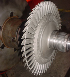
Turbine and Impeller

Image credit: www.romaga.com

Turbocharger Dismantling Procedure

Compressor Side Removal:
Dismantling should always be started from the compressor side.
1) First remove the filter silencer assembly or compressor inlet casing from position.
2) Remove the compressor end cover and drain plug on the compressor side.
3) Remove the suction cover and measure the critical clearance .It is the distance between the compressor end cover mounting face and shaft end .Mark it as K.
4) Pull the rotor shaft towards the compressor side until the impeller comes in contact with the insert and determine K2.
1. Impeller clearance L = K - K2
5) Thrust the rotor shaft towards the turbine side until the turbine disc and nozzle ring comes in contact with each other and measure K1
2. Disc clearance M = K1 - K
6) The above measured clearance is very important as this will determine the proper functioning of the labyrinth seal between the impeller and exhaust shield and also the alignment of the shaft.
7) Remove the lube oil pump assembly after removing the pump locking plate.
8) Remove the bearing nut and bearing nut washer.
9) Fix the bearing pulling tool in position and slowly tighten it. This will pull the ball bearing assembly out. Care should be taken while removing bearing to avoid any damage to the bearing and rotor shaft end threads.
10) Mark the position of the bearing in position to put it back as it is while assembling.
11) The ball bearing assembly should not be disturbed in any case. If it is damaged, the whole assembly should be replaced with the manufacturer's new part.
12) Now remove the compressor outlet casing with diffuser.
13) Remove the impeller nut and impeller washer.
14) Remove the impeller and inducer from position.

Turbocharger turbine side dismantling procedure for overhauling,for repairing damaged turbine blades, for cleaning cooling water spaces is detailed in the second page of the article "Overhaul and Repair of a Marine Turbocharger."
Turbine Side Removal
1) Remove the turbine end cover with sight glass on the turbine side.
2) Measure the clearance between the turbine end cover mounting face and shaft end.
3) Check the axial deflection of the pump disc cover. The permissible axial deflection of the pump cover is 0.05 mm.
4) Check the rotor shaft by turning by hand.
5) Remove the pump disc locking plate.
6) Loosen the lube oil disc cover and pump washer on the lube oil pump disc by removing the bolt.
7) Remove the outer shaft end nut and tab washer and then remove inner shaft end nut.
8) Remove the lube oil disc from position.
9) Loosen the bearing nut and bearing nut washer and remove from place.
10) Fix the bearing pulling tool on a resilient mounting and slowly tighten it, and this will pull the roller bearing on turbine side slowly out.
11) Care should be taken while removing the bearing to avoid damage to the shaft outer end threads and bearing.
12) Do not disturb the bearing assembly as improper bearing position may misalign the rotor shaft.
13) Before removing, put punch mark on the bearing in position so that it can be put back as it is.
14) Remove the turbine inlet casing from the turbine outlet casing.
15) Now the whole rotor shaft can be pulled out from the compressor side. While pulling out the shaft, care must be taken to avoid damage to the turbine blades and labyrinth sealing arrangements on the shaft.
16) Remove tab washer and remove seal plate to the turbine outlet casing.
17) Remove shroud ring and shaft seal from the turbine outlet casing.
18) Remove nozzle ring assembly from the turbine inlet casing.
Finally remove the air seal adjusting screw, anti-corrosion zinc assembly, sand cover, and other various accessories in position

# Various books, study material and other online sources has been refereed prior to writing this article but no part is copied or produced  from any of the source but explained same thing in better detailed way.

Author Amit                                                                     

If you have any problem with the content contact us! we will act ASAP


What is marine boiler and Boiler system on oil tankers.

What is marine boiler and how it works on oil tankers.

A boiler is a closed pressure vessel, in which water vapor is produced from distilled water / feed water. All boilers have a furnace or a combustion chamber in which fuel is combusted to release energy. Air is provided in the boiler furnace for assisting the combustion of the fuel. A large clearance between the combustion chamber and the water allows the transfer of combustion energy to the water, as heat. The boilers are equipped with a steam drum and a water drum, which ensure steam and water respectively, can be separated. It should also provide a variety of accessories and to ensure that the fuel, the supply of air and water is to meet the steam requirements.

VARIOUS USES OF STEAM ON SHIPS

For main engine propulsion/turbines (in case of steam ships)
For power generation (to run steam turbo generators)
For running auxiliaries (in case of steam ships)
For soot blowing and for the steam atomized burners.
For fresh water generation (Evaporators)
For fire major fighting (steam drenching)
For heating duties (ME fuel oil heater, Galley supply, Purifier, Calorifier, Galley, Accommodation heating, Sea chests tracer lines for pipeline heating)
For cargo heating
For fuel tank heating
For deck machineries
For running Cargo pump turbines
For operating bilge, stripping and other steam driven pumps.
For tank washing in tanker ships and general cleaning.
For using as a steam ejector media for ejector pumps and vacuum devices
For Driving steam driven deck machineries like winches etc.

Pressures used:
The working pressure used in marine boilers will vary from boiler to boiler as required.For Tanker Vessels Medium pressure 17-30 bar(normally 16bar).

Boiler system in oil tankers:

Boiler system in oil tankers

Due to the high demand in the oil-Tankers, high capacity composite boilers or Dual pressure boilers are used. The main reason for the introduction of double pressure boiler is the use of modern boiler water pipes of high yield, without fear of load damage or contamination of Fuel oils. The basic construction is made of a D-Type boiler design upon which is mounted a Steam/Steam generator drum. Steam heating by the main boiler warms the water in the steam generator which full fill all the requirements for a propulsion pump, the heating load and fuel tanks and all other tasks of turbines.

The drum is initially filled with the primary quality of feed water and is well balanced. Make-up is limited to small amounts due to leaks and the fuel pump can be simple. An example of this could be an alternative pump driven by steam or air. The chemical treatment/dozing is simple and requires only minimal for the addition or rinsing. The above design shows super heater in the system but this is usually installed where the generated steam is required for the turbine alternators.
Secondary drum.

The U-shaped heating elements welded through the door of the shaft and at the end covered with the drum head. The tubes are well supported. In the lower part of the housing a manhole can be installed to allow access to the heating elements. The secondary drum also acts as a receiver for the exhaust gases of the steam boiler. Typical pressures above 63 bar (278degC) for the primary and 23.5deg (219degC) for the secondary. Primary pressure of 35bar (242degC) and closer to 15bar high pressure (198degC) proved to be sufficient to drive turbines for cargo oil pumps on tankers.

Composite boilers

On another hand Composite boilers are a combination of oil boilers and exhaust gas economiser. When the diesel engine is at full load, the fuel burner starts only when the steam demand is higher than the production of steam from the exhaust gas of diesel engines. Composite boilers are so arranged that these can generate steam on Main engine exhaust gases or by burning oil in the furnace. In most cases the gas flows are kept separate each having its own uptake this permits the oil firing to be used in conjunction with the engine exhaust gases. By this means the output of steam can be maintained independent of the engine power.

Most of the tank type auxiliary boilers can be modified for composite firing, the modification consists of an additional tube nest added to basic oil fired design, the engine exhaust gases are circulated thru this tube nest so providing heat for generation of steam. In port stays boiler pressure is controlled by start/stop of burner at required pressure, and during sailing the pressure control is by excess steam dump valve.

But on which principle D-type water tube boiler work?

D-type water tube boiler

This boiler has 2 drums, an integral furnace with wall mounted burners and is often referred to as ‘D’ type boiler because of its shape. The furnace is at the side of the 2 drums and is surrounded on all sides by water tube walls. These water wall tubes are connected either to upper and lower headers or a lower header and the steam drum. The larger steam drum is placed above a smaller water drum , The two drums are connected to a large number of pipes of small diameter, which carry feed water. These small diameter pipes are known as the generating tubes that provide the main heat transfer surfaces for the generation of steam. The water circulates between the two drums with the aid of large diameter downcomers. The superheater is located through several rows of screen tubes covered between the drums. The fireproof material is used in the manufacture of the furnace, the burner wall and behind the water walls. The fire-resistant material acts as an insulator, which prevents heat loss. The boiler is also provided with a jacket for the combustion air, around the air control registers, which are surrounded by the burner.

# Various books, study material and other online sources has been refereed prior to writing this article but no part is copied or produced  from any of the source but explained same thing in better detailed way.

Author Arpit Singh                                                                             Article requested by: bilal ahmad