IMO project adressing Blast Water Mangement completes.

IMO project adressing Blast Water Mangement completes

A project promoting the implementation of an international treaty stemming the transfer of potentially invasive species in ships’ ballast water has been concluded at a meeting of stakeholders from governments, the shipping industry and UN bodies, the International Maritime Organization (IMO) said. 
The final meeting of the GloBallast Global Project Task Force (GPTF) was held in Panama City, Panama, from March 16 to 17.
The IMO has been carrying out the GloBallast Partnerships Programme in collaboration with the Global Environment Facility (GEF) and the United Nations Development Programme (UNDP).
Launched in 2007 after an initial four-year phase, the program has been assisting developing countries to reduce the transfer of harmful aquatic organisms and pathogens in ships’ ballast water and implement the IMO Ballast Water Management (BWM) Convention, scheduled to enter into force in September 2017.
According to the IMO, the final meeting highlighted the legacy elements of the GloBallast project, which are expected to be sustained by its main stakeholders following the formal closure of the project in June 2017.
Specific examples include GloBallast training packages to support the capacity-building needs of countries implementing the BWM Convention. The regular BWM R&D Fora, which promoted the development of innovative ballast water treatment technologies, are also expected to continue after the project’s closure.
Within the project, regional task forces were formed in 12 developing sub-regions and regional strategies and action plans on BWM were developed, involving more than 100 countries. To date, six of these action plans have been adopted through the regional cooperating institutions.
GloBallast has also facilitated capacity building at the national level, helping to establish national task forces and assisting with drafting and adopting the national legislation in 80% of its lead partnering countries. This has supported many of these countries to ratify the BWM Convention, the IMO said.
The meeting in Panama also promoted the key role of the project’s lead partnering countries within their respective regions to sustain regional BWM implementation, and explored funding mechanisms that could finance future capacity-building needs, the IMO further said.
“Through GloBallast, governments, industry and other stakeholders have acted to further improve the environmental and socio-economic sustainability of shipping and worked to reduce its negative impact on marine ecosystems,” Stefan Micallef, Director of IMO’s Marine Environment Division, said.
“The GEF-UNDP-IMO GloBallast Programme has played a key catalytic role in preparing countries and the shipping industry for the implementation of the BWM Convention, which will reduce the significant ecological and economic damage, lost livelihoods and human health impacts often caused by invasive species,” Andrew Hudson, Head of the Water & Ocean Governance Programme at UNDP, commented.
The GPTF meeting was hosted by the Panama Maritime Authority and attended by 43 participants.


#Note: The following article is property of (World Maritime News) http://worldmaritimenews.com  and re-used after taking due permission.

# Source: http://worldmaritimenews.com/archives/216224/imo-project-addressing-marine-bio-invasions-completes/


Starting & Reversing System in 2 Stroke marine Diesel Engines

Starting air system in two stroke engine

Large two stroke marine diesel engines are started by starting air at 30 bar pressure. The starting air is inserted in...............


.........

Some part of the post is shifted to our new blog check shipfever.com

..................

REVERSING SYSTEM :

Reversing system in two stroke marine diesel engine

A marine diesel engine directly coupled to the propeller shaft must be reversible. The reversing system must be capable of turning the engine in opposite direction by compressed air.

The condition which must be satisfied are :
1.  change in the sequence of starting air admission
2.  set the fuel pump timing to reverse running direction
3.  air inlet valves (if fitted) and exhaust valve timing as per the reverse direction.

In four stroke engines to obtain all these changes on the same camshaft, a separate set of astern cams is fitted. Each astern cam is fitted to camshaft adjacent of ahead cam.
To engage the correct cams for ahead and astern running the camshaft slides axially. The incline between the ahead and astern cams allow the cam rollers to transfer from one cam to the other.

The axial movement is controlled by camshaft reversing gear, which is usually a piston operating in hydraulic cylinder fitted to the camshaft. Locking devices and safety cutouts ensure that camshaft has carried out its full axial movement before the engine can be restarted.  Hydraulic system can be fed from the main engine lubricating system.
In some engines, the axial movement of the camshaft is carried out by air pressure. Pneumatic servomotors are usually supplied with air from starting air system.

The two stroke cycle can also be illustrated on a timing diagram.

Timing Diagram of I.C engine | 2 stroke marine


1 -2 Compression 1. approx 110º BTDC
2 - 3 Fuel Injection 2. approx 10º BTDC
3 - 4 Power 3. approx 12º ATDC
4 - 5 Exhaust Blow-down 4. approx 110º ATDC
5 - 6 Scavenging 5. approx 140º ATDC
6 - 1 Post Scavenging 6. approx 140º BTDC

Large two stroke engines have scavenge ports which control scavenge timings. This will be symmetrical and hence will be unchanged when reversed. Engines operating with constant pressure turbo-charging system have almost symmetrical exhaust valve timing, so no change in timing is necessary for exhaust cams.

Fuel pump timings need to be re-adjusted when the engine is required to run in reverse direction. Two such methods are explained below:
  • By moving fuel pump cam follower positions (B&W)
In MAN B&W engines fuel pump cams are fixed but the follower is repositioned relative to the crankshaft and this Retimes the fuel pump to new direction.
When reversing is carried out, air enters the pneumatic reversing cylinder and the piston is moved to the other end of the cylinder. The cam follower moves across and attains a position which changes the fuel pump timing in the new direction.
The link is self locking in either position and a limit switch is fitted to each pump to indicate the position of cam follower.

  • by moving the fuel pumps cam (Sulzer)
 Sulzer RTA engines have oil pressure operated hydraulic “lost motion” servomotors on the camshaft which rotate the fuel pump cams to their astern position.
Fuel pumps and their cams are grouped in pairs along the camshaft and a servomotor is fitted for each pair of adjacent cams.
Servo motor uses a rotating vane, which when oil is supplied under pressure through the drain, will rotate through the lost-motion angular distance to change the fuel timing for astern operation
 “Lost motion” is the term used to indicate that the timing has been retarded, through a given angle with respect to new direction of rotation.

Reversing mechanism in Sulzer

Since same cam is used for both ahead and astern movements, the camshaft is rotated by hydraulic servomotor through a definite angular distance. The angle through which the cams are turned is known as “Lost Motion Angle”.

The servomotor consists of pair of vanes, fitted on the camshaft which moves between another pair of vanes fitted within gearwheel rim. By putting lubricating oil under pressure between opposite pair of vanes, the camshaft is moved related to the gearwheel and engine crankshaft. The relative movement changes the fuel pump timing for ahead and astern operation and change the firing order.The rotation of Camshaft is independent of crankshaft and hence it is called as “Lost Motion”.


Author marineGuru


fuel injection system & Diagram in marine diesel engine

The fuel injection system is one of the most important parts of a marine diesel engine. A fuel injection system does the work of providing the right amount of fuel to the engine cylinder at the right moment. It is also extremely important that the fuel injected inside the engine enters the cylinder at the right combustion situation for the highest combustion efficiency. It is for this reason that there is a need of a measured fuel supply system which times and monitors the delivery of the fuel and oil in the combustion chamber. This timing device helps to have a perfect atomization of the fuel. The device is known as fuel injector.

Fuel injection is done with the help of cams and camshaft. The speed of the cam shaft is same as the engine speed in a two stroke engine and half the engine speed in a four stroke engine. The adjacent fuel injection system diagram gives a broad view to the reader regarding the fuel injection system. The faded sketch shows the engine in the background whilst the dark coloured schematic represents the fuel system. This helps the reader to understand the concept in conjunction with the given theory.

Types of Injection :
  • Jerk Pump
  • Common Rail
Jerk Injection : The most common system used on modern diesel engines. The fuel pressure is built up at a fuel pump in a few degrees of rotation of the cam operating the plunger. Fuel is directly delivered to spring loaded injectors which are hydraulically opened when the fuel pump has generated sufficient pressure.

BOSCH JERK PUMP

Jerk fuel injection, marine disel engine
Jerk fuel injection
The pump consists of a cam operated single acting plunger of a fixed stroke. Helical springs are fitted to return the plunger on its down stroke and to maintain contact of follower on the cam.

A helix or scroll is machined on the plunger which is closely fitted inside a barrel.
As the plunger moves down the suction and spill ports on the barrel open and fuel flows into the barrel. As the plunger moves upwards a pressure is created immediately when the suction and spill ports are covered. This is the pressure at which the injector is set to open.
Injection continues until the point the helical groove on the plunger uncovers the spill port. The high pressure in the barrel is immediately connected to low pressure of fuel suction. The injector will close once the pressure falls below injector opening pressure.

The regulation of quantity of fuel is effected by groove on the plunger. The plunger is free to rotate in the barrel and rotation is achieved by a rack and pinion arrangement. Rack is fitted to the pump to engage with a pinion machined on the outside of the sleeve. As the plunger rotates the position of the helix relative to the port in the barrel will change thus controlling the amount of fuel delivered.

In some pumps a non return spring loaded discharge valve is fitted to ensure positive seating of fuel injector needle and reducing cavitation within pump.

Timing : Adjustment of injection timing is carried out by varying the relative height of plunger and suction/spill ports in the barrel. Lowering the plunger has the effect of retarding the injection. Raising the plunger advances the injection.
Fuel pump Timing Control, marine fuel injection system
Fuel pump Timing Control

Timing can be adjusted by moving the cam with respect to the shaft. Rotating the cam on camshaft in its ahead direction of rotation will cause advancing while rotating opposite with respect to ahead direction of rotation will cause retarding of injection.
Alternatively the fuel pump casing itself may be lowered or raised on its mounting to give the corresponding effect.

Advancing will cause early injection with result of
  • rise in maximum pressure.
  • improvement in specific fuel consumption.
  • exhaust temp will be less
  • improvement in power.
  • high thermal efficiency.

Retarding the cam gives late injection with
  • low peak pressure.
  • high exhaust temp
  • low thermal efficiency
  • possibility of afterburning.


Fuel pump Timing Control Diagram, marine fuel injection system


A-Pump spill closes (approx.-8o)
B-Fuel injector opens (approx. -4o)  Pressure approx 300 -350 bar.
C-Spill opens (approx. 12o)  Max pressure approx 600 bar
D-Fuel injector closes (approx. 16o)
G- Injection period (approx. 20o)


    Author marineGuru


    Basic line diagram of Engine Room for junior engineer and rating.

    For every engineer officer, preliminary theoretical knowledge of day to day operations and piping systems is important for taking cognizance of complicated machinery operations.
    The junior rank is generally the in-charge of daily transfers related to sludge and bilge waters, under the directions of the second engineer and thus he should begin his enterprise with the same approach.

    These line diagrams vary from ship to ship, this may give you a general idea how to draw a line diagram in your tar book to identify various parts.


    lube oil system main engine

    lube oil system for turbocharger

    fireman system


    seawage plant system


    line diagram of blidge system

    line diagram of sea water cooling system

    fresh water system

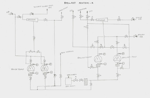
    line diagram of blast system

    line diagram of basic camshaft lube oil system


    Author marineGuru


    UPTAKE FIRE in MARINE DIESEL ENGINE and boiler

    UPTAKE FIRE


    Engine exhaust gas contains particulates which consist of partially burnt fuel and/or lubricating oil and ash. These particulates can form deposits on boiler Tubes. Especially during prolonged low load operation, which reduces exhaust gas velocity, it may lead to higher soot deposition. It may be due to
    burning poor quality fuel,
    poor combustion due to defective injection equipment, or
    inefficient fuel treatment.

    These deposits on the tubes may get heated and rise above self ignition temperature. Soot deposits may be ignited by glowing carbon particulates in the exhaust gases. The ignition temperature of the soot is usually less than 400 C, however if the deposits  stick, it could fall below 200 C. 
    Soot fires can occur after the engine has shut down, therefore it is important to maintain water circulation after shut down.

    The fire will be indicated by
    dark smoke coming out of funnel
     large rise in exhaust gas temperature after the boiler.

    Action  :
    If fire does occur the engine should be stopped immediately and the turbocharger air intake covered to starve the fire of air.
     Ensure full water circulation is maintained.
    A small fire may burn itself out as the heat will be conducted away by the circulating water.
    If water washing system is fitted, it can be used to extinguish the fire.

    Prevention :

    Soot Blowers : Soot blowing should be carried out on regular basis to ensure soot and ash deposits do not build up on tubes. It should be carried out more frequently when the engine is operating at low loads or when fuel has high ash content. It should be carried out after water washing of main engine turbocharger (water side).

    Water Washing of Exhaust gas Boiler : The combustion of residual fuel results in formation of slag. These slag gradually build up on the boiler tubes. Soot blowing keeps these deposits at low levels, however it does not reach all areas of boiler. These slag are soluble in water and can be removed by hot water washing.

    Author marineGuru


    SCAVENGE FIRES | Cause, indication, Action and prevention

    Scavenge fire in marine diesel engine
    Scavenge Fire
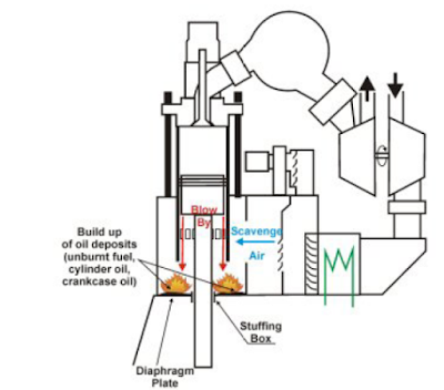
    For a scavenge fire to occur there must be present combustible material, oxygen or air to support combustion and source of ignition.

    The combustion material for scavenge fire is oil.
    • It can be cylinder oil which is drained from cylinder spaces,
    • crankcase oil carried upwards due to faulty stuffing box or
    • fuel oil from defective injectors, injectors with incorrect pressure settings,

    The oxygen necessary for combustion comes from scavenge air which is available in abundance.

    CAUSES :

    The source of heat for ignition can be due to piston blow past which may be due to 
    • sticking or broken piston rings or
    • excessive liner wear.
    • Faulty combustion due to late injection or incorrect atomization may also be responsible as it will cause blow back of exhaust through the scavenge ports.

    INDICATIONS : 

    • Loss in power and irregular running of the engine
    • High exhaust temperature of corresponding unit
    • High local temperature in scavenge trunk.
    • Surging of turbochargers
    • Sparks and smokes emitted from scavenge drains
    • External indication will be given by smoky exhaust and soot and carbon particles in the exhaust.
    • In modern UMS ships, temperature sensors are fitted which will activate alarm and cause automatic slow down of the engine.

    ACTION :  If a scavenge fire is detected the immediate objective is to contain the fire within the scavenge space of the engine and to prevent or minimize the damage to the engine.
    • Reduce the speed of the engine
    • Cut off fuel to affected cylinder.
    • Increase the cylinder lubrication of the affected cylinder to prevent seizure.
    • Close all the scavenge drains to prevent the discharge of sparks, smoke in the engine room.
    • Personnel should stay clear of the scavenge relief doors.

    A minor fire will shortly burn out without damage, and conditions will gradually return to normal. The affected units must be run on reduced power until inspection of scavenging trunking and overhaul of cylinder and piston can be carried out at earliest opportunity. The actual cause of fire should be investigated.

    If the scavenge fire is a major one or if there are chances of fire spreading to the adjacent spaces,
    • engine should be stopped, normal cooling should be maintained
    •  turning gear should be engaged and engine turned or turning gear.
    •  Fire extinguishing medium should be applied through the fittings in the scavenge trunk. This may be CO2, dry powder or smothering steam.
    • Boundary cooling of the scavenge manifold may be necessary.
    • Scavenge manifold should not be opened until the engine has cooled down.

    PREVENTION :
    • Scavenge trunk must be periodically inspected and cleaned. Any build up of contamination to be noted and rectified.
    • To carry out inspection through scavenge ports at regular interval and monitor the condition of piston, piston rings and liner.
    • Scavenge drains should be cleaned regularly and ensured that they are clear.
    • Piston rings must be properly maintained and lubricated adequately so that blow by is prevented.
    • Ensure cylinder lubrication timing and quantity is correct.
    • Fuel injection equipment to be maintained in good condition.
    • If the cylinder liner wear has reached its maximum limit the possibility of scavenge fire will not be reduced until the liner is renewed.

    Author marineGuru


    What is Crankcase Explosion? Cause, Indication and Action

    CRANKCASE EXPLOSION
     
    For a explosion to occur there must be source of air (oxygen),fuel and ignition. Under normal conditions the oil/air concentration is too weak and the possibility of ignition by heat source is too low.
    Crankcase oil should normally have a high flash point (above 200 C) and this must be maintained to reduce risk of explosion.

    CAUSES :

    The cause of the crankcase explosion is a hot spot or overheated part within or adjacent to the crankcase of an operating engine. A local hot spot may arise due to overheating of

    bearings, piston rod gland, timing chain,
    hot combustion gases or sparks from piston blow-past in engines where no diaphragm is fitted, or
    from fires in scavenge spaces.

    PRIMARY EXPLOSION :

    If a hot spot exists, some oil will come in contact with it and will be vaporized.
     It will circulate to cooler parts of the crankcase and will condense to form a white oil mist.
    The oil droplets in this white mist are very small. If this oil mist should now circulate back to the hot spot in such concentration, it will be ignited and a primary crankcase explosion will occur.

    SECONDARY EXPLOSION :

    The explosion causes a flame front and pressure wave to accelerate through the crankcase, vaporizing further oil droplets in the path.
     The pressure shock wave  may build up sufficiently to rupture crankcase doors, if not relieved.
    Also, if relief valves do not reseal after lifting, it will cause air to enter into the  crankcase resulting into another flammable mixture to be developed leading to secondary or major explosion.
    The secondary explosion is more violent and can cause crankcase doors to blow off and start fire in engine room.

    INDICATION :

    Detection of hot spot can be by
    use of temperature sensitive probes within the crankcase near the bearing oil returns.
     More commonly, the white mist can be detected by Oil Mist Detectors, which operates visual and audible alarms.

    ACTION :

    In case of detection of hot spot,
    the engine must be slowed down and stopped and bridge should be informed accordingly.
    The engine must be turned on turning gear with lubrication oil supply on.
     Under no circumstances the crankcase doors should be opened unless the engine is sufficiently cooled. Once the engine is cooled, stop main LO pump, the crankcase should be opened and ventilated.
    Inspect all bearings and running surfaces for any hot spots.
    Inspect the bottom of crankcase for any for any signs of bearing metal.
    Investigate the cause for the hot spot and engines to be started only after the fault is rectified.

    OIL MIST DETECTOR 

    Oil mist Detector block diagram
    Oil Mist Detector
    An Oil Mist detector is fitted to monitor samples of the air and vapour mixture taken continuously from the crankcase of the diesel engine. Such a device will detect the presence of oil mist at a concentration well below the level at which explosions may occur, giving a warning in time to take necessary action.

    The detector consists of two parallel tubes of equal size, each having a photoelectric cell at one end, which generates an electric current directly proportional to the intensity of light. Two identical beams of light from a common lamp are reflected by mirrors to pass along the tubes onto the cells which are then in electric balance.
    One tube is sealed to contain clean air and is termed the reference tube. The other, the measuring tube, has connections through which samples of the crankcase vapour are drawn by an electric extractor fan.

    Sampling points should be fitted to each cylinder crankcase and their connections are brought to rotating selector valve which is driven from fan motor. This repeatedly connects each sampling point to the measuring tube in sequence.

    If a concentration of oil mist is present in the sample, light will be obstructed before reaching the cell of measuring tube. Electric balance between the two cells will be disturbed and an alarm will be operated. The rotary valve stops to indicate which sampling point has high concentration of oil mist.


    Author marineGuru


    CHARGE AIR COOLING AND AIR COOLERS

    Charge Air Cooling :

    The air density determines the maximum weight of fuel that can be effectively burned per working stroke in the cylinder, it also determines the maximum power that can be developed by the engine.

    The increase in air density is fractionally offset by increase in air temperature resulting from compression by turbochargers. Much of this potential loss can be recovered by charge air coolers. Charge air cooling has double effect on engine performance :
    • By increasing the charge air density it increases the weight of air flowing in cylinder and
    • by lowering the air temperature it reduces maximum cylinder pressure, exhaust temperature and thermal loading.
    Air Cooler : The most common type of cooler is water cooled design with finned tubes in a casing carrying sea water over which the air passes. For efficient cooling velocity of air should be low and cooling area large. This is obtained by making air inlet connection divergent and outlet is convergent to restore air velocity.
    Condensation of moisture in the compressed air will occur during cooling and a drain is fitted to the outlet side to allow the condensate to be removed. The drain should be kept open and its discharge noted, this will also indicate if a cooling water leak has occurred.
    The cooler consist of a tube stack of aluminum brass tubes bonded into two brass plates. Cast iron boxes are attached to the tube plates and allow sea water circulation. The air seal is maintained by a rubber joint ring.
    Thin copper fins are soldered to the outside of the cooler tubes. The air will pass between the plates which greatly increase the area of heat transfer. Temperature and pressures are recorded at each inlet and discharge.
    Too high air outlet temperature will increase the exhaust temperatures and will cause loss in efficiency due to reduction in air density.  Air at very low temperature will cause thermal shock when in contact with liner and pistons and will increase chances of corrosion.

    charge air cooler
    Charge air cooler


    Author marineGuru